Bill Bedford 14:1 gearbox kit
by Russ Elliott and Ted Scannell
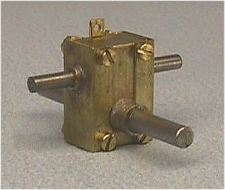
This is an etched brass 14:1 gearbox kit for a 1.5mm transmission shaft and a 2.0mm driven axle.
Note: The 8.6mm dimension over the outside faces of the axle bearings may be reduced in subsequent production batches.
|
Parts list:
1 etch 2 transmission shaft bearings. 1.5mm i.d. 2 axle bearings, 2mm i.d. length of 1.5mm steel transmission shaft 1 axle gear, 1 worm 4 bolts and 4 nuts, 14BA To be supplied by modeller: Axle (2mm) and wheels |
Recommended sequence of construction
General notes
- Acquaint yourself with the recommended sequence before commencing construction. For example, it is easier to fit the bearings before detaching the relevant parts from the fret.
- Soldering is necessary only to fit the bearings into the body plates and to secure the torque reaction control link eye.
- Body folds should not be fillet soldered, as this may adversely affect the fit of the end plates.
- All bends are on the inside except the link eye.
- In the course of construction, the end plate(s) need to be attached and detached to the main body: the 14BA bolts may bite into the etch cusps sufficiently for the purposes of these preliminary assembly checks, but some users may prefer to clean out the holes with a broach or a 0.95mm drill for clearance before starting, or just before final assembly.
| 1 | Before removing the washers provided on the etch, ensure the 1.5mm transmission shaft and 2mm axle are an easy fit, easing the washers with a small broach if necessary, and making sure any new burrs formed by the broaches are eliminated by rubbing the washers lightly on some wet and dry abrasive paper. |
| 2 | Cut the 1.5mm steel shaft to your desired length: 13mm is recommended for a single-ended drive, 17mm for a double-ended drive. Carefully deburr the cut ends of the shaft, and polish a radius onto the edges, because any sharp edges may cut into the inside surface of silicone tube UJ pieces. |
| 3 | Attach the worm to the 1.5mm steel shaft: Loctite 222 Screwlock is recommended. Check that the worm clears the access holes in the body inner end plates, broaching them out if necessary. |
| 4 | Clean any burrs off the sides of the axle gear with fine wet and dry abrasive paper. Fit the axle gear to the centre of your axle: the axle gear should be an interference fit, so no adhesive should be necessary*. If the fit is too tight, a few very light turns using a broach or the tip end of a 2mm reamer will ease the fit. Ensure the axle gear rotates without wobble when the axle is rotated.
* If inappropriate lubricants are used in service, there is a possibility that the plastic gear may eventually swell. If this possibility causes concern, then fitting by reaming and securing with Loctite 222 is recommended instead of relying on an interference fit. |
| 5 | The bearings should now be fitted to the side and end plates and this is most easily done before the plates are detached from the fret. The flange of each bearing is on the inside of the plates. Use a minimum of solder, and ensure the flange is flush to each plate. Ensure there is no solder on the non-flange (outside) of the axle bearings, or on the flange (inside) of the worm shaft bearings, where this would impede the fit of the side plates. |
| 6 | If you feel you will need to lubricate the gears after the gearbox has been installed in a chassis, drill a small hole in the middle of either the top or bottom (depending on your choice of gearbox orientation) area of the main body plate. |
| 7 | Detach all four plates from the etch and fold sides, ends, and top and bottom, to as near to 90 degrees as possible. The torque reaction eye on the main body plate should be folded over (fold on the outside) and secured with a spot of solder. |
| 8 | Test fit (do not solder) the two sides of the gearbox together, and determine how many 2mm bore etched washers either side of the axle gear are necessary: there should be a very slight amount of clearance/sideplay so that the axle can rotate freely. |
| 9 | With the axle and its gear in position, test fit the end plates to the body, using the 14BA bolts: do not solder. The bolts may thread and grip the cusps of the holes sufficiently for these preliminary assembly checks. Check for squareness of assembly. The tightness of the bolts may affect the clearance of the axle gear between its side plates, so the bottom bolts may need to be adjusted by say a ¼ or ½ a turn so that the axle can continue to rotate freely in its bearings – bear this in mind when fitting the nuts. |
| 10 | Detach one end plate. Starting with two or three 1.5mm washers either side of the worm, slide the worm and its shaft into position and re-attach the end plate with the bolts. Judge the amount of to and fro backlash in the transmission shaft to determine the number of washers required: the objective is to get the slightest amount of backlash (typically 0.003" to 0.005") while ensuring the transmission shaft can continue to rotate freely. |
| 11 | When satisfied with the free rotation of the transmission shaft, disassemble one end plate, and grease the gears. 'Tri-Flo' grease or any low stiction plastics-compatible grease is recommended. Reassemble the end plate. Fit the 14BA nuts, taking care not to overtighten them. Lightly lubricate the four bearings. |
| 12 | Your gearbox should not require running in, but any assembly of this type should be treated gently for the first hour or so of use, following which the gearbox can be stripped down, washed out, and regreased if you really want to. |
© Russ Elliott and Ted Scannell
issue 1, October 2002
| Return to top of page | Safety, privacy and cookies |