Secondary springing for bogie vehicles
by Russ Elliott
IntroductionThis page describes some implementations of secondary springs on 4mm scale bolsterless bogies.
|
Our primary springs are often referred to on the prototype as 'axle springs', and our secondary springs are referred to as 'bolster springs'. |
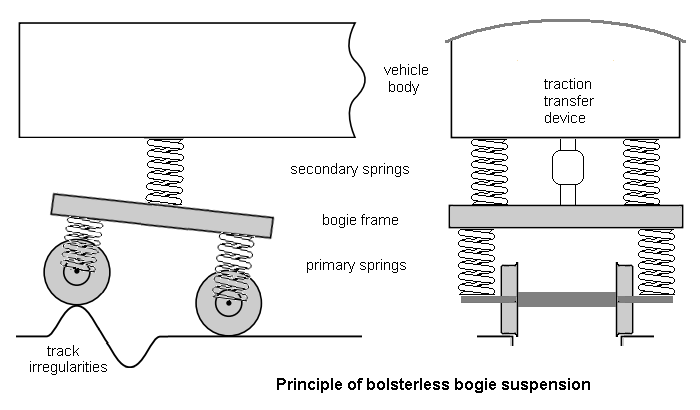
The function of secondary springs on the prototype is to ensure good ride comfort for passengers. The secondary springs support the vehicle body and absorb the vertical and lateral motions of the bogies arising from the vibrations generated by track irregularities, the most serious of the lateral vibrations being caused by a wheelset or bogie taking up an oscillating slewed position on the track ('hunting'). The secondary springs also minimise the impact of centripetal forces when running on curves at speed.
On small-scale models, the prototype phenomenon of bogie hunting is largely absent, and the effects of centripetal forces do not have the same significance, so the function of secondary springs is therefore to complement the primary springs in decoupling the vehicle body weight from track and wheel irregularities (the latter being far worse than the prototype), and to dampen and minimise body roll ('wobble').
On prototype bolsterless bogies, bogie yaw is strongly resisted to minimise hunting, and achieved through the horizontal deformation of the bolster springs (and often assisted by horizontal anti-yaw dampers), with the bogie frame rotating about a centre pivot through a 'traction transfer device', which takes the horizontal traction force. In contrast, model bogie yaw needs to remain as free as possible.
Unlike prototype springs, model springs do not need additional damping devices, either because of the friction present between typical model components or because of the particular mass-frequency characteristics involved in small-scale models.
Implementations of secondaries on models
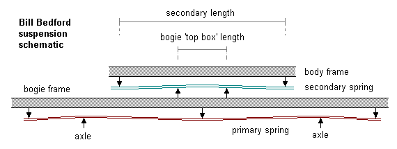
The diagram adjacent shows the principle of the Bill Bedford secondary system, where the secondary springs are attached to the underside of the bodyframe, and bearing on to the top box of the bogie itself. In the Pendlenton bogie, the secondaries are attached to the bogie frame, bearing up against a transverse plate mounted in the body underframe.
In both implementations, the axis of the secondaries is longitudinal.
Strengths of secondary springs, and body roll sensitivity
The strength of the secondary springs, together with their lateral spacing, will determine the roll characteristic of the body relative to the bogie frame.
The sensitivity to body roll is largely determined by the lateral spacing. Body roll will be more prevalent and pronounced as the lateral spacing gets smaller.
| Type | Length | Spring diameter | Secondary strength * |
| Pendlenton | 50mm | 0.020" (as supplied) | 0.25N/mm |
| Pendlenton | 50mm | 0.024" | 0.5N/mm |
| Bedford | 20mm | 0.014" | 1.0N/mm |
| Bedford | 20mm | 0.015" | 1.25N/mm |
| Bedford | 20mm | 0.016" | 1.6N/mm |
| * double this value for the bogie as a whole
The secondary springs applied to Bachmann Mk1 coaches in MRJ 200 are 0.18N/mm each (0.36N/mm per bogie), but please note these bogies are not fitted with primaries. | |||
Bogie pitch performance
The deflection value δ of the secondary will depend on its strength and the relationship between the secondary length L and the length of the bogie 'top box' (or equivalent chassis bearer if the secondary is mounted the other way up).
This relationship will affect the pitch performance of the bogie. If x is small compared to L, the bogie will be able to pitch freely. As x gets larger in relation to L, pitching will be resisted owing to the mechanical lever advantage being given to one end of the bogie frame as the top box tilts and bears up against a different position on the secondary. In the context of a 150g vehicle on 34mm bogie wheelbases, and for a secondary length of 20mm, a value of 9mm for x has been found to provide a good compromise setting. The strength of the primaries will also play an important part of the pitching process.
Roll plane frequency responses of rigid and secondary-fitted vehicles
[text and video to follow]
to be continued
© Russ Elliott
February 2011, released (awaiting video) March 2014
| Return to top of page | Beam menu page | Safety, privacy and cookies |