Making all-metal wheels
by Bill Newton
|
|
Editor's note: This page first appeared in 1998 but has not been publicly visible for some years. As a member of the Manchester Model Railway Society, and with a model engineering background, Bill came under the influence of modellers such as Sid Stubbs and Norman Whitnall who encouraged a 'do it yourself' approach. The wheels illustrated here are to 4mm scale, but the method is equally applicable to other scales and gauges. Dave Booth, another member of the Manchester Model Railway Society, has done an excellent page on wheelmaking based on the methods of Sid Stubbs, which can be seen at http://mmrs.co.uk/technical-articles/making-wheels/.
|
Introduction
Wanting a pickup system less fiddly and more robust than wire wipers and being a member of the Manchester Model Railway Society where split-chassis pick-up is de rigeur, I decided to try it myself with all-metal wheels. I did not fancy fretting out the spokes from a solid blank and so decided on a three-part construction consisting of a centre 'spider' from brass where the spokes would be formed by milling with two slitting saws spaced apart by the spoke thickness, a rim turned from steel using a circular form tool to machine the tread and flange, and a wheel boss.
The wheels I have produced so far are of simple form having a flat wheel centre. The method could also be used for wheels with dished spokes with a little extra work. Vee profile rims as used by Stanier on the LMS would be rather more awkward and the best procedure here might be to put the work into making one master and then have wheels investment cast in nickel silver. Minimal finishing should then be required.
|
Making the wheel centres
The procedure is as follows:
- Mount a length of brass bar in the three jaw chuck and turn sufficient length to about 0.020" (0.5mm) over the diameter required for the wheel centre.
- Drill from the tailstock chuck a few thou under the axle diameter.
- Face the end of the bar and part off to the thickness of the wheel centre (not including boss). Repeat for as many parts as needed. For such operations, it is a great advantage to have a rear toolpost with a parting tool mounted (upside down). The position of the facing tool is adjusted on the top slide so that after facing; the cross slide is simply wound back to part off at the correct thickness.
- If you are going to press the wheels onto the axles, put a reamer into the wheel blanks just far enough to give the correct interference fit. I felt more comfortable with soldering wheel to axle and reamed through to axle size.
- Make up a stub mandrel to mount the wheel blanks for finishing the outer diameter to size. This ensures better concentricity than finishing to size at stage one as the drill is liable to wander a little if put in some distance.
- Mark the spoke positions on one or more blanks. A number of blanks are soldered together for milling – I found a stack of six to eight worked well. A blank should be marked out for each such stack. I have made an indexing attachment using lathe changewheels which can be fitted to the back end of the lathe mandrel. It has found many applications including marking these spoke positions with a pointed stick in the toolpost. In the absence of such a tool, you will have to use your ingenuity.
- Solder up a stack of blanks with the marked one on top using an aluminium rod for registration. Solder a boss, crank or plain on top to serve as a depth guide when milling. A gas torch/stove will be required.
- Make up a fixture as shown in picture 1 and mount the stack for spoke milling on the vertical slide. My fixture has two vertical posts, one for each wheel bore diameter and a simple clamp. Prepare a spacer to separate two slitting saws by the spoke thickness and set up on a mandrel as shown.
- Align the blank with the top of the stack at centre height and mill to depth. Raise the vertical slide screw to clear through to depth. Reset and repeat for all spokes, noting the cross slide index for uniform depth and following the crank boss profile on driving wheels. See picture 2.
- Unsolder the wheel centres and finish spokes with file and emery.
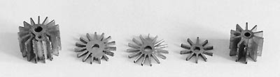 Freshly milled and finished centres |
|
My lathe is a Myford ML7 of 1967 vintage. This machine will turn 7" diameter over the bed and 20" between centres and so is larger than many would consider adequate or appropriate for 4mm scale work. The 640 rpm top speed is rather low for working on small pieces (2500 to 3000 rpm would be better) but it has very useful milling capacity using the vertical slide for this scale. Another most useful accessory is a back toolpost that will mount to the cross slide and carry a second tool (most often a parting tool) upside down. This facilitates batch production of like parts. Once you have the basic lathe with vertical slide, this and other accessories can be made yourself. You may not wish to spend time on this sort of thing when the objective is a model railway but it will pay off in the long run. |
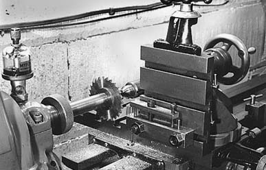
Picture 1 Setup for milling spokes in a stack of seven wheel centre blanks |
Picture 2 Spoke milling in closeup |
|
Making a form tool for the tread/flange
The circular form tool is the most suitable. The profile is formed by turning, the operation a lathe is best suited to. The cutting edge can be re-sharpened right around the periphery of the tool to give a lifetime of accurate use. I have used free-cutting silver steel for my form tools and it is well worth taking the trouble to obtain some. It machines beautifully to leave give an excellent finish. I obtain mine from Chronos though doubtless there are other suppliers. I made a tool of male form first and used this to machine a female form to be used to turn the wheels.
 Form tool cutting edge
|
A slice about 1/8" thick is drilled and parted from the stock bar. I used 3/4" diameter and drilled 1/4" although a little smaller would suffice. The slice is mounted on a suitable arbor and the tread/flange profile carefully machined. Harden this form by heating to bright red heat and plunging into a bucket of water. I suspend the disc from a loop of wire, heat with a gas torch, then agitate in the water to give most rapid cooling. To temper the tool, brighten with fine emery and heat again but more slowly this time. When the colour starts to change, quench it again in the water. It should be a light straw colour when quenched. A segment is ground away as shown in the diagram opposite to give the cutting edge. Make up a holder as seen in picture 3. I used 3/4" square steel clamped under the toolpost and drilled for tapping 1/4" BSF directly in the lathe. Again, smaller would suffice but I always tend to overengineer. Use a tri-square sighted along the lathe bed to line up.
Prepare another slice of the silver steel between 1/8" and 3/16" thick, mount on the arbor in the lathe chuck or collet and machine the female form using the tool just made. Use a slow speed with plenty of lubricant to get the best finish – I used the lowest speed on back gear. Once again, harden, temper and grind the cutting face.
|
Making the wheel rims
The rims are made in two stages, first producing a ring which is then mounted on an arbor for the profile to be turned with the form tool. Each of the two setups allows a number of rims to be processed quickly.
- Chuck a length of mild steel of sufficient diameter for the wheel and turn down a length of it to about 0.015" (0.4mm) over the diameter over the flange.
- Drill the bar to the nearest drill size you have under the diameter of the wheel centre. If you do not have a drill anywhere near that size, it doesn't matter – it will just take a bit longer to bore them out to size.
- Grind a knife tool to the form shown in the adjacent diagram and set in the toolpost facing the chuck. This is used to face the rim, bore out to size and put in a rebate if required to simulate the rim form. The relief under the cutting edge must allow the tool to enter the drilled hole.
- The rear toolpost is put in position with its parting tool – it really is indispensable, and the top slide set so that the separation between the knife tool and the parting tool will produce a rim of the correct thickness.
- Bore out the drilled hole until a wheel centre will just go in. You only need to go in a little over 2mm. Make a note of the cross slide index so that following rims can be bored to the same setting.
- Put in the rebate if required, again noting the cross slide and top slide indexes used.
- Skim the face of the rim and wind the cross slide out to part off. Check the thickness of the rim and adjust the top slide to correct the error. With the settings now established, you can quickly turn out a pile of rims.
- Make up an arbor to mount in the chuck or collet to hold a wheel rim.
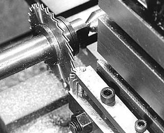
- Mount a rim on the arbor and set your form tool square in the toolpost. Picture 3 and picture 4 show the setup.
- Line up the form tool on the rim, lock the lathe saddle and feed in carefully on slow speed with plenty of lubrication. Make a note of the cross slide index when the correct diameter is reached. You should have left only a few thou to take off.
- The rest of the rims can now be mounted on the arbor in turn and the tool fed in to the same index.
|

Knife tool showing ground away front clearance to go into drilled hole
|
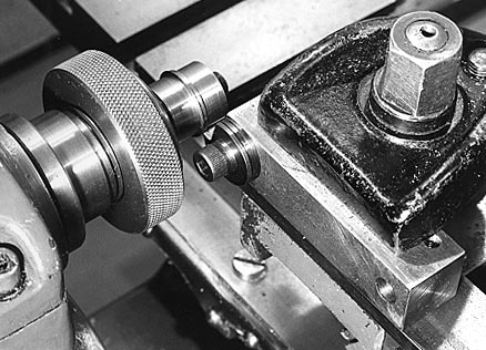
Picture 3 Turning the wheel tread/flange with a circular form tool
|
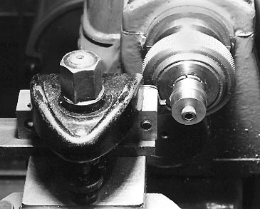
Picture 4 Another view of the form tool
|
|
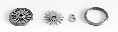
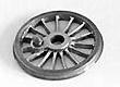
A finished wheel and its component parts
|
Making the wheel bosses
Bosses for bogie and tender etc. wheels are a simple turning job. Again, the rear toolpost will allow a pile to be turned out quickly when the correct settings have been found.
Bosses for drivers with crankpins are a filing job using a hardened former made from 1/16" thick gauge plate. I pick up this and other useful materials at model engineering exhibitions although mail order is of course available. There are not too many stockists of this sort of thing in small quantities. Two small pieces of the gauge plate were drilled 1/8" (axle size) and a second hole to suit your preferred crankpin system at a separation given by the crank throw. Two buttons were turned to sit in these holes and provide the correct diameters for each end of the boss. The gauge plate pieces were thus profiled and then hardened. Pieces of brass sheet of suitable thickness are cut, drilled using the gauge plate formers, clamped between the formers three or four at a time with shafts through the holes for registration, and the profiles filed up.
To assemble the wheel, the parts are clamped flat onto a block of aluminium with a peg inserted to register the centre and boss, and soldered up. I used a spot of solder paste at each spoke/rim joint and heated with a gas torch.
|
© Bill Newton
first published September 1998
revised January 2007 for CLAG site
updated 22 November 2007 to include reference to Dave Booth's article on the MMRS site
|