Brassmasters' sprung hornblocks
by Russ Elliott
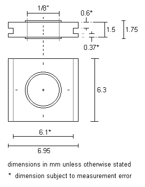
Introduction This page gives details of the revised Brassmasters' 1/8" bore sprung hornblock, included with coil springs in their 3-axle pack A021. The dimensions given here were measured from sample products, and are thus unofficial: they are intended as a constructional helper in chassis-planning and making.
The hornblock These hornblocks are intended to slide in frame or hornguide slots of nominal 6mm width.
The transverse width of the slot in the hornblock is, by calculation, 0.53mm. The roll plane freedom of the block is constrained by this slot width: we are looking for a roll freedom over the required vertical distance of hornblock travel, nominally 0.5mm downward and somewhat less than that upwards, such that the slots in the hornblock do not 'grip' the frame to impede that smooth movement. Experimentation shows that the roll plane freedom is right on the limit (a slope of approximately 1:30) with frames of 0.5mm thickness, and some remedial work, by lightly chamfering the inside faces of the hornblock, may even be required with a nominal 0.45mm frame thickness. (Metal thickness in many etched kit chassis framework is nominally 0.45mm. For 'decorative grade' thin metal sheet, as used in etched kits, there is typically up to a 10% tolerance on the nominal thickness.)
As supplied, the axlebore is a very tight 1/8", so a little work with a reamer will be required. This initial tightness is extremely useful if the hornblocks are being mounted on chassis subplates being positioned by coupling rods and extended axle jigs.
I could not detect any longitudinal or vertical asymmetry in the placing of the bore with respect to the hornblock perimeter.
Note the transverse asymmetry of the hornblock slot, a feature that can be exploited to control or alleviate wheelset sideplay in critical situations. If necessary, the annular ring can be filed off one side of the hornblock to obtain more sideplay.
Note: The hornblock drawing shown was done on 12 May 2003. An official drawing of the hornblock appeared on the Brassmasters site in September 2003.

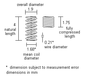
The spring Approximately 1kg was required to fully compress six of these hornblocks mounted in a chassis built by John Brighton. Over the full compression length of 2.25mm, this gives an average springrate of approx 0.72N/mm. By calculation, using the approximate wire and mean coil diameters, the estimated number of active coils as 6, and using a modulus of torsion of 75GPa, the average springrate is 0.65N/mm, which correlates very well with the measured figure, given that the estimate of the number of active coils is necessarily subjective to a degree if an integral value is used.
What does all this mumbo-jumbo mean in real terms? Well, it means that our 80g axles (using 4g/ton as an approximate 4mm scale weighting factor, and taking the example of a 20ton prototype axle weight) will deflect its two springs in the region of 0.5mm to 0.6mm. If you use more than 4g/ton, the deflection will be in linear proportion. These hornblocks function in proper suspension mode, and are not 'spring-assisted'.
Setting out the hornblock in the frames

|
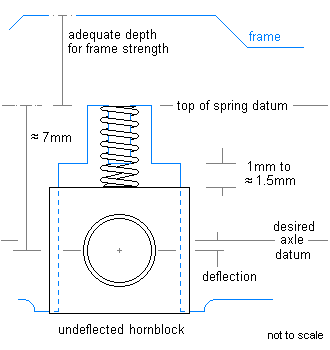
The Brassmasters' hornblock is suitable only for frames having a depth adequate to accommodate the spring.
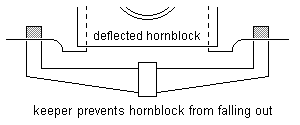
Some careful marking out and cutting will be required to make suitable frame cutouts, derived from the desired axle datum line. The consistency of the top of spring datum is important. The spring can be retained by a small tongue cutout in the frame. Some form of keeper, e.g. a piece of wire or a spring etch/casting, will be necessary to prevent the hornblock falling out of the chassis. 
|
Here's a couple of pics of a Comet Ivatt 2-6-0 being constructed in P4 in John Brighton's 'Steamline Sheffield' loco works. Because of the particular frame spacers John used, the annular ring on the outside of the hornblock has been filed off, to ease the sideplay situation. John found that the springs on this chassis, being etched as part of the sideframes, could be eased aside to insert the hornblocks. The rolling road is from ZTC Controls.
.jpg) photo: John Brighton
photo: John Brighton
.jpg) photo: John Brighton
photo: John Brighton
This page may be amended further to reflect manufacturer's and constructors' comments in due course.
© Russ Elliott
issue 4, October 2003
| Return to top of page | Safety, privacy and cookies |