Class 31 sprung chassis
by Ted Scannell
Note. The information on this page relates to the pre-production stages of what became Bill Bedford's Class 31 chassis, some pictures of which can be found here.
|
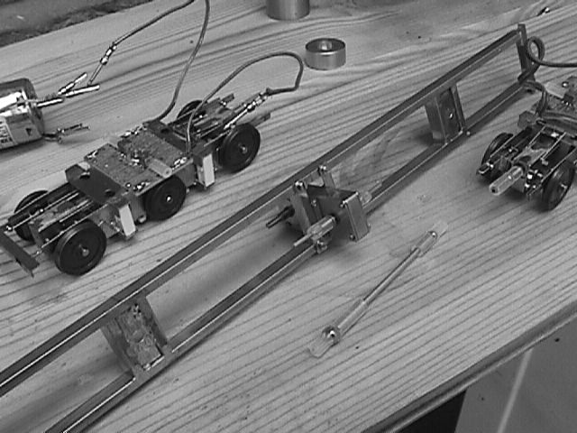
Picture 1 shows the main chassis rails; they are made up from 3/16" x 3/32" rectangular brass tube, cut to an appropriate length and spaced at the bogie pivots by S4/P4 15mm frame spacers. These spacers are supported by 15mm lengths of the same rectangular tube. The end pieces, which are designed to support buffer beam strengtheners, came from the bogie etch, having been left off the inner ends of the bogies to allow room for the drive.
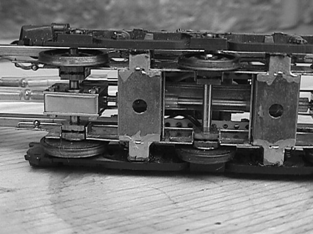
This view is of the underside; the stretchers that carry the transfer gearbox (Exactoscale 2:1 two stage, assembled with tube and screw spacers instead of those 'orrible pins) are cut from 1/8" 'L' section brass, as are the brackets fixed to the 'box. In both cases they are drilled 1.5mm to accept 14BA screws, which allows for a degree of adjustment. This adjustment is desirable 'cos the 'box slides from side to side across the chassis... |
|
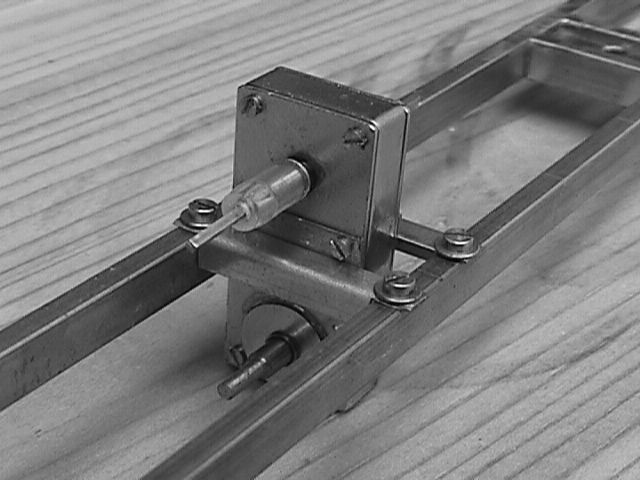
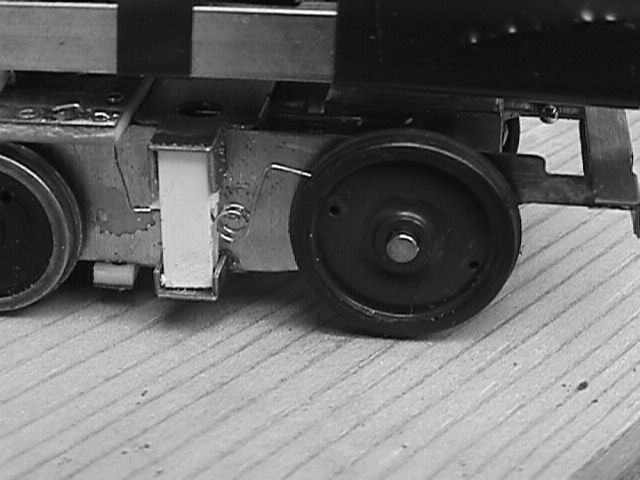
| Picture 2 gives a closer look at this, chassis still inverted. The ends of the shafts have been turned down to 1.5mm, from the original 3/32", to accept my standard UJs. (Sorry all those without access to a lathe.) Owing to space restrictions, there are no ball bearings in the output UJs of the transfer box, but instead short lengths of 1/32" nickel-silver wire are soldered into a piece of 1/16" square section tube, making a composite ball/shaft assembly. This method appears to work just as well... |
|
|
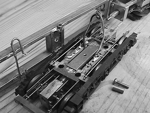
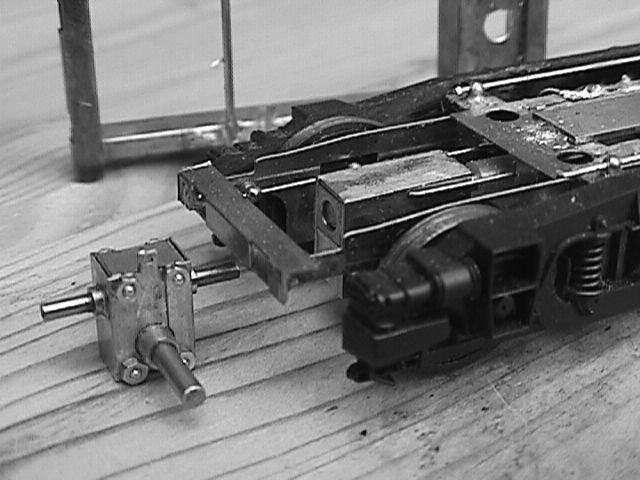
Picture 3 shows the view from above of the complete assembly.
Note the gearbox is resting against one side of the chassis in this shot. Future plans include replacement of the silly little flywheel with something much more substantial, possibly geared up, and driven from the opposite side of the transfer box with similar shafting to that shown between motor and gearbox. |
|
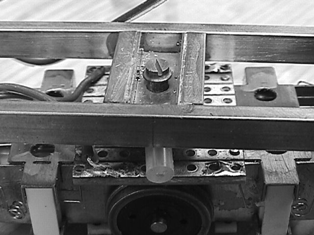
| Picture 4 – the underside view of the assembled mechanism. The lines on the chassis rails are datum points scribed during the marking out procedure. |
|
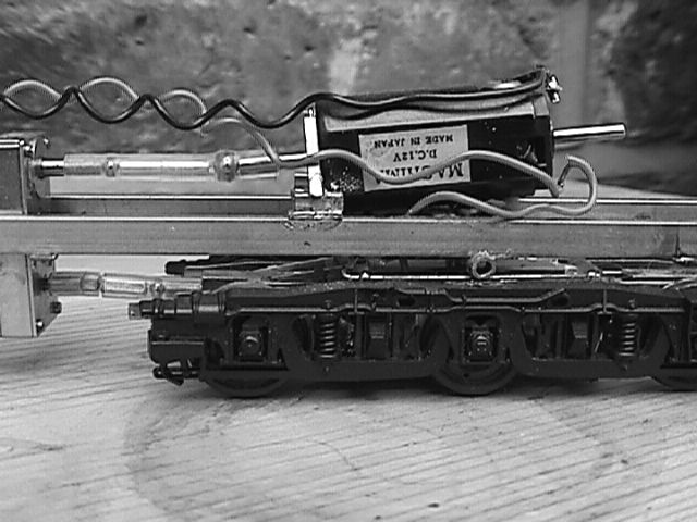
| Picture 5, side view. |
|
|
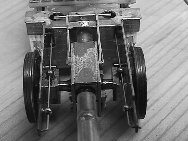
Picture 6, specifically showing a disconnected bogie cardan shaft. The square tube is 1/16" brass, the silicone tubing 3mm x 1mm bore, the ball bearings 2mm dia.
Now to the bogies... |
|
|
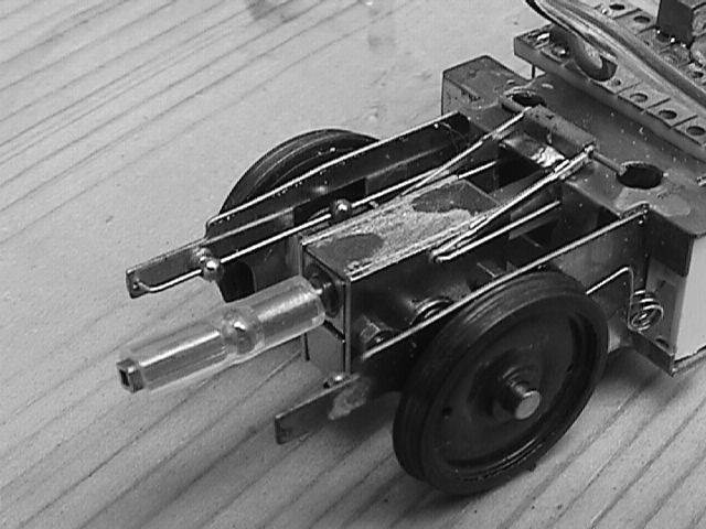
Picture 7 shows the revised version of the bogie top mounting and secondary suspension. And I finally got round to fitting some cosmetic sideframes...
Most of the original veroboard has gone, and been replaced by a pair of vero strips which simply carry the pickup connections. The mounting plate is a piece of 1/16" brass, tapped M2 and soldered to the bogie stretchers. A 'proper' secondary suspension design has now been installed. Handrail knobs are soldered to the outer ends of the stretchers and a piece of guitar string fitted. One end is bent over slightly to prevent it slipping out, and the other end is deformed by crushing after installation. The slides on the main chassis frame are made up from a piece of 3mm x 2mm brass tube, with a flat filed on to it, cut to fit, and soldered to the frame tubes. The design deflection required was estimated at about half that of the primary springs, so 0.25 mm was considered desirable. With a span of 28mm, and an estimated load of 100g, wire of 0.7mm (28 thou) section gave a theoretical deflection of 0.14mm, and wire of 0.6mm, (24 thou) a deflection of 0.34mm. I settled for the softer of the two. It helps to broach out the holes in the knobs a little, even though they are nominally 0.6mm already, as the wire does need to be free to slide in the holes. |
|
| Picture 8, the underside. You can just make out the drive shaft above the centre axle. Much tidier now that the crazy veroboard mounting arrangement has gone. |
|
|
Picture 9, the pivot and secondary suspension. This is the original secondary suspension, for comparison. The pivot design has not changed.
The pivot needs to allow complete freedom in vertical translation, and all of the rotations, pitch, yaw and roll. While doing this, it needs to totally restrict longitudinal and lateral translations. A hole in a piece of thin brass... The tube is 3mm o.d., the screw M2. The length of the tube doesn't really matter much. |
|
|
Pictures 10 and 11 show the torque reaction control links. I know that some modellers don't think these necessary, and I have shown that this chassis will function without them, but not so well, as undesirable vertical loadings are introduced into the gearbox input shafts. Including control links is simple enough provided their function is understood and they are planned for. And it is better practice.
The links themselves are the long loops from an MJT screw coupling etch, and the anchor is made up from a short piece of 1/16" square brass tube with a 0.6mm brass pin soldered into it. The pivots need to be free, but with the minimum of slop. The assembly is made up, and with the gearbox held at the desired angle, the tube is fixed to the bogie bolster with a lowmelt solder. Picture 10 also clearly shows the way that the end handrail knob spring anchors have been moved by 4mm towards the centre of the bogie, compared with the earlier version. This is at both ends. At this end only, use is made of the redundant holes by bending the wire to 90 degrees and cutting it off flush, or nearly so, and then popping it through the end hole to retain it. This hole should be large enough, dependant on how far it is from the anchor point, that it does not inhibit the movement of the spring. |
Viewed from here it can be seen that the hole in the bolster that allows the drive shaft through also guides the torque reaction link between the boxes. Because the hole is 6mm wide, and the gearbox 5mm wide, these links are sprung into place and require no further fixing. Note also that the bearings are free to move along the axle, their transverse positions controlled entirely by the spring. For a 'scratch' version, Alan Gibson guides can be used upside down, without the wires or the nut, screw and coil spring, and they work better. |
| Picture 11 – this is the inner axle of the bogie, the wire attached to the top of the gearbox (Exactoscale 18:1) is Alan Gibson 0.45mm brass, with the ends bent to 90 degrees at exactly wheelbase distance, and popped into a hole drilled in the centre of the gearbox side about 0.5mm clear of the top edge. It joins the two gearboxes together so that the shaft distance between them remains constant, so a simple piece of 1.5mm brass rod with a UJ at each end can drive them, no sliding section being needed. |
|
|
Picture 12: the pickup assemblies. The material is 1/8" 'H' section styrene rod. It just happened to be a perfect fit in the space that Bill provided. I drilled a 0.3mm hole in the web, 2mm from the top, to take the 33SWG phosphor-bronze wire that I used for the pickups.
They were wound on a jig made with a piece of hardwood, a piece of 1.5mm rod, and a Peco track pin. They wobbled about in an unacceptable manner even after being bent down on both sides of the web, so I found some 1/16" material of the same section and filled the hollow of the 'H' with that, down to where the pickup wire was bent back to the horizontal. Once the plastic solvent had dried off, I filed the top part back to its original size and shape. Once you know what you are looking at, they can be made out on pictures 5, 7, 10 to 12. These pickup units can be assembled and adjusted separately from the bogie, to which they are not fixed, but are retained by the cosmetic sideframes and the (unstressed) solder joint to the veroboard. This way I get a rigid, insulated, serviceable mounting, hidden behind the outer frames, that keeps the wheels clean for me as well as collecting the current. |
For further details of the construction of these pickups, see here. |
|
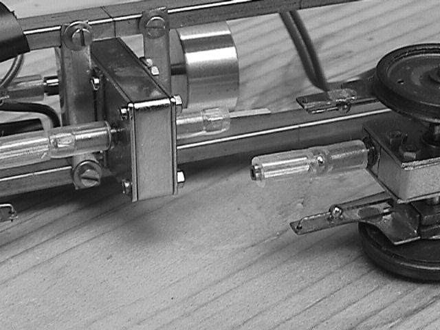
Picture 13 – the Bill Bedford motor mount and Mashima motor. The revised secondary suspension can just be seen in its running position. The motor mount needed a non-standard installation as it was designed to be used with wider set frame tubes as on the production version. The much shorter cardan shaft is made up from aluminium tube, and has had no effect on the locos ability to traverse tight curves smoothly and without hesitation.
A much refined version of this chassis is now available as a Bill Bedford kit. |
|
|
Performance The bit I can't take a picture of. And it can be very subjective.
A most important feature is that the central transfer gearbox can slide transversely across the chassis. This greatly reduces the side loading on the final drive UJs while travelling over curves, and allows the chassis to be driven slowly through a 1:4 crossover without any noticeable speed reduction. In order to allow for this, the drive to the top part of the transfer box needs to be as long as possible to keep the change in angle of the UJs as small as possible, as the gearbox moves, to give maximum freedom to the bogies in the yaw plane. The Cannon motor that I used is not an ideal choice. It revs a bit slowly. Scale speed at 12V is probably less than 40 mph, giving superb low speed control and presence, but I'd like it to go a bit faster, and not occupy the cab space. Hence it's fugitive mounting arrangement. With an all-up weight of 260g, and a tractive weight of 180g, less than half that of a Bachmann class 24 or 25, the drawbar pull at point of slip shows 50g, or 28% tractive efficiency. On full power, pull was 67g, or around 37% efficiency. At ExpoEM, it moved that raft of eight carriages with inside bearings on the test track, but slipped to a stop on the gradient change, possibly due to the carriage wheel flanges touching the floors. On the level at CLAG, with the all-up weight increased to 305g, it walked away with nine pinpoint-bearinged Mk1s; it would be interesting to see how it would cope with such a train on a gradient, and with a few more volts than were available at Expo. |
| Picture 14 – the Bill Bedford 14:1 gearbox. While the original 2:1 transfer box with 18:1 final drive gearboxes gave very close control, the maximum speed of less than a scale 40 mph was not really satisfactory. Bill has therefore designed a 14:1 final drive box, which coupled with his new 12:20 transfer box gives a much more reasonable 23:1 overall ratio, compared with the original 36:1. |
|
| Picture 15 – the Bill Bedford gearbox, showing the integral tag for the attachment of the torque reaction control link. |

|
|
Photographs
For those that are interested in the photographic details, I recorded the images on this page with a Sony Digital Mavica MCV-FD7 still camera, direct to 3.5in floppy in mono mode to jpg format. Lighting was natural daylight in a conservatory roofed with triple polycarbonate, giving an ideal diffusion for such a subject. |
|
List of bits
For now, the basic list. Drive wheels and axles are Alan Gibson carriage wheels (selected) fitted to modified (sides drilled 0.6mm for reaction links, spacer pins replaced with 2 x 1 mm tube and 14BA screws; 4mm of shaft ends turned down to 1.5mm) Exactoscale 18:1 gearboxes. Idler wheels are 13mm disc, 1 axle Gibson, 1 axle K-M (I know, I know – they were in stock, though). Bearings are Alan Gibson standard type, drilled 1/32" to accept Markits handrail knobs. Bogie frame is a test etch from Bill, capped with a bit of Veroboard, and modified to reduce the outer spans of the outer axles by 4mm. The other mods to Bill's etch were to widen the central holes in the bolsters by 1mm overall to take the stress off of my torque reaction coupling links, to deepen the clearance in the side holes of same to make sure that the spring wire did not foul, and to drill extra holes in the tops, above the spring anchors, so that I could see better when threading in the spring wires. Those in the pictures are 13 thou guitar strings. The all-up body weight is now an estimated 420g, of which around 300g is tractive, giving somewhere near 80g on the drawbar, about the same as a re-wheeled Bachmann class 24/5. M2 nuts and machine screws sleeved with M3 brass tube through P4 frame spacers form the bogie pivots. Chassis rails are 3/16" x 3/32" rectangular brass tube. Drive shafting is 1/16" brass rod except between transfer gearbox (Exacto 2:1 2-stage) and bogie inner gearbox, where it is 1/16" square brass tube and 1/32" nickel wire. UJs are 3mm o.d. x 1mm bore silicone rubber tubes with 2mm ball bearings stuffed up'em. Secondary suspension uses the same tubing, stuffed into 1/8" square section brass. Body fixing, which has not yet been photographed, is 0.9mm brass wire shaped into two long loops, soldered across the chassis ends to line up with the slots under the doors in the Airfix/Dapol bodyshell. These can be bent to set the buffer height, so the suspension does not need any critical height adjustments. Lima bogie sideframes are glued on with silicone adhesive to complete what looks something like a class 31. That should be it. If I've left out anything, please ask. Cheers! Ted. |
© Ted Scannell
October 2002
| Return to top of page | Safety, privacy and cookies |