Some Gibson wheels come without pre-drilled crankpin holes, the 4'7½" GWR wheel being one of them. Consistency in the drilling of the crankpin throws is an important factor in obtaining smooth running.
Two methods are shown here, a 'luxury' method with a milling machine, and the more traditional method using a simple jig and a vertical drill.
Drilling crankpin holes in Gibson wheels
by 'Buffalo'
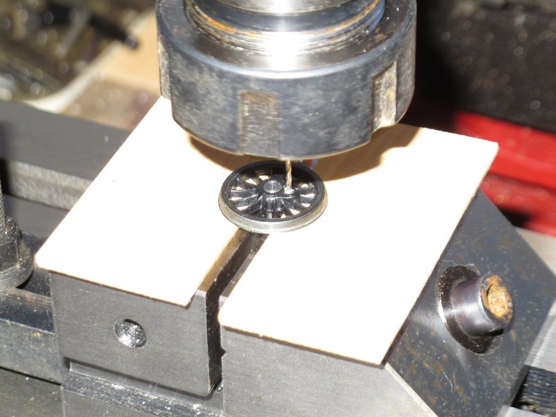
Milling machine
With the milling vice loose on the table, a piece of 1/8" rod is clamped in the vertical V-groove and the other end inserted in a suitable collet. The vice is then clamped to the table and, after removing the rod, the table is offset by the prototype crankpin throw (10" in this particular Pannier case). The crankpin hole is then drilled, each wheel being either already mounted on an axle or on a dummy slightly undersize axle. Packing pieces are used on top of the vice to stabilise the rim of the wheel.
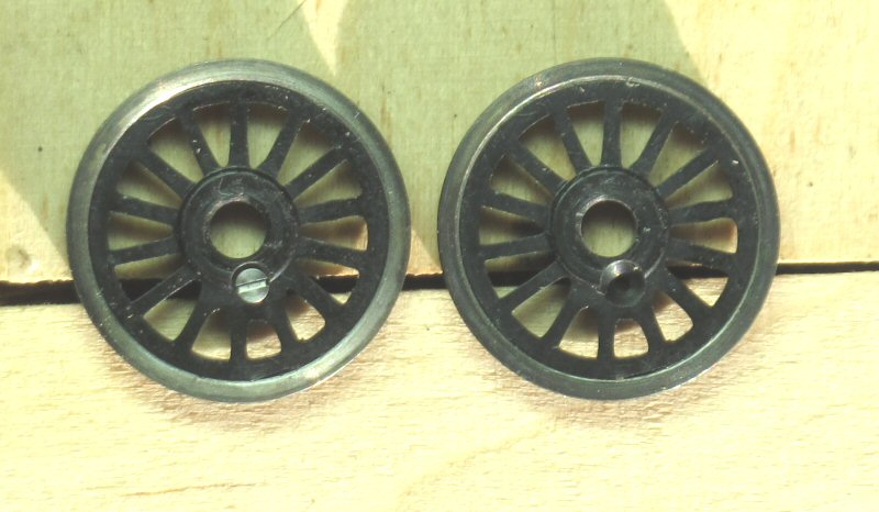
There is a small dimple molded into the wheel at the nominal crankpin throw position, and some care was needed in starting the small drill. Tim Venton advises drilling the wheels from the rear to avoid the potential problem of the drill wanting to wander into the moulded dimple.
Metal jig
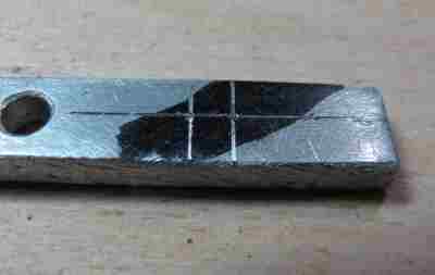
Take a piece of brass or steel about 3mm thick and mark off two points at the crank throw distance.
(The one in the photo is actually a scrap piece of aluminium, but something like the earth pin of a 13A plug would be ideal.)
Drill both points 0.75mm, then open out one to 3.1mm or 1/8". If possible, do this in a drill press to ensure the holes are vertical and parallel, otherwise do what you can by hand.
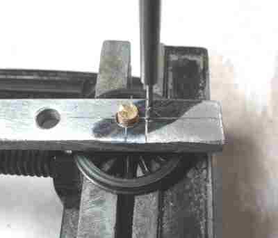
Next, take a piece of 1/8" brass rod, put it in a drill chuck and polish it with some emery cloth. The idea here is to reduce the rod's diameter very slightly so that it will be a good sliding fit in the wheel's axle hole.
With a vice holding the reduced diameter rod, the wheel is slid on to it, and the jig is inserted on top, aligning with the orientation of the wheel's crankpin boss. It can be a bit tricky to line up the drill with the jig's crankpin hole, but the thickness of the jig will ensure the drill remains vertical and at a consistent pitch.
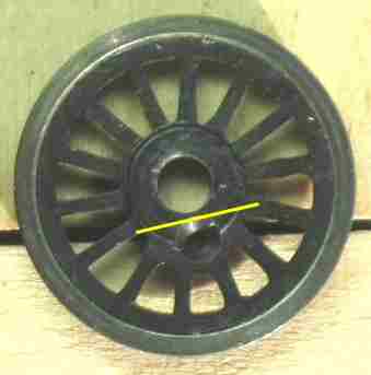
On the rear of the Gibson wheel, crankpin holes align with or are very near the edge of the moulded boss. This part of the boss needs to be removed or countersunk so that the head of the crankpin screw does not foul the axle bearings or the screw is not forced off centre. Two common solutions are carving away some of the boss with a scalpel (as per the yellow line on the picture on the right) or countersinking the hole. I chose the latter approach (using a 2.5mm drill) and this was aided by my setup in the milling machine.
Countersinking can be achieved perfectly well with a drill held in a pinchuck, and it's always wise to have good view of the process to judge the right depth of the countersinking.
The picture below shows countersunk holes, and an inserted crankpin screw clearing the face of the boss.
© 'Buffalo'
15 March 2013
| Return to top of page | Safety, privacy and cookies |