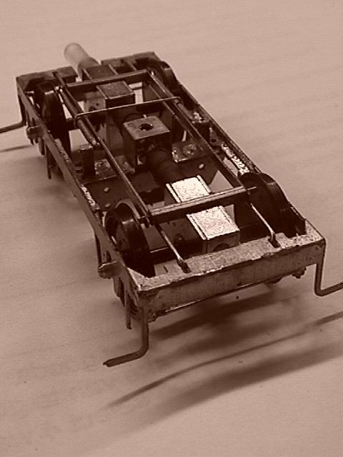
The prototype twin-gearbox drive bogie, already a few months old, which I snapped with Dave Haswell's newly acquired digital camera on its first CLAG night out on 16 July '98. The bogie has experimental cardan pieces and Alan Gibson 3' disc wheels, and was later modified for experiments in 3rd rail pickup operation.
Pendlenton drive bogies
by Russ Elliott
Introduction
This article describes Ted Scannell's original work on 4mm scale drive bogies using Pendlenton sprung bogie parts and Exactoscale gearboxes.
With the objective of setting the transmission system completely below floor level, Ted started developing these bogies a few years ago, and despite regular cajoling from people like me who thought this was important work, he never got round to putting pen to paper. So before we all get too old and forget why and how it was done, and why it all seemed rather exciting at the time, I decided to put at least some of the record down.
These units, or developments of them, are likely to form the core of the DMU drives on Green Street.
Drive bogie development continues, and some constructional aspects detailed in this article have been superseded by later developments; this page may therefore be updated from time to time.
Application area
|
Pendlenton bogies, like Masokits, Scalefour CCUs and MJT torsion units, are designed for pinpoint outside bearing use with standard 26mm long pinpoint axles. For drive bogie applications, the Pendlenton is therefore suitable primarily for lighter vehicles such as DMUs and EMUs. Parallel bore outside bearings could be fitted, in conjunction with non-standard axles, but it is likely that drive bogies for heavier locos will be better addressed by the use of inside bearing hornblocks. |
Drive configurationsThese bogies have been built in double gearbox 2-axle drive and single gearbox 1-axle drive versions.Where one axle is driven, both bogies of a vehicle are powered. To avoid the extra constructional complications in getting the transmission pieces past bogie pivots, it is easier to power the inner axles of a vehicle; the alternative option of driving the outer axles can however lessen the angular displacements required in the transmission pieces between the chassis and the bogies. |
|
Pendlenton bogie suspensionPendlenton bogies are sprung. There are no beams; there is no 3-point compensation. These bogies do not equalise axle loads (nor are they intended to). |
|
The springs and their settingsPendlenton bogies have two sets of springs:
The ride characteristics of the vehicle will depend on the gauge of spring chosen for the secondary spring. Ted found that it was better to err on the 'strong' side, and chose 0.013" and 0.024" steel guitar strings for the primary and secondary springs respectively (instead of the 0.011" and 0.020" recommended by the manufacturer) for his DMU application. Some trial and error will be required to get the best combination of ride characteristics for a particular vehicle's weight. Keith Norgrove found that the ride characteristics of Pendlentons were just as good with the secondary springs removed. If you want to know more about calculating an actual deflection of a particular leaf spring, refer to my Deflection of Beams articles. |
Exactoscale worm gearboxesExactoscale worm gearboxes were available in 3 ratios: 18:1, 30:1 and 40:1, and could be assembled for either 2mm or 1/8" diameter wheel axles. Exactoscale transmission shafts are all 3/32" as standard, although a variety of adaptors are available to step down to smaller metric standard shaft diameters.The small size of the 18:1 gearboxes makes them ideal for drive bogie applications. Putting Exactoscale gearboxes together is not everyone's cup of tea, but they are excellently-made precision units, and great value for money. The official assembly instructions are not however to everyone's liking, so here's a set of alternative instructions by Ted (with some contributions by others), plus pics of a set of gearbox parts and a completed box. |
Postscript note. Please note the above dimensions and reference numbers relate to pre-2005 Exactoscale worm gearboxes. Exactoscale produced a newer range of gearboxes post-2005, but their availability from Exactoscale's new owners is unknown.
|
|
Torque reaction control for worm gearboxesAny gearbox on an axle that is allowed vertical movement with respect to a bogie or chassis frame requires torque reaction control. This control must allow the gearbox and its axle to move up and down and to swing. The gearbox will try to rotate around the transmission axis, but there is no point in controlling this torque vector, as we want a degree of axle swing, and in anycase the value of this torque is comparatively small. The crucial torque reaction we do want to control is to prevent the gearbox from its natural inclination to rotate around the driven axle.These requirements are simply and best achieved by holding the gearbox to the bogie frame by an attachment that is longitudinal and horizontal. A horizontal torque reaction attachment is the ideal. In practice, a slight deviation from the horizontal will not matter, since the up and down movement required of the gearbox is small, and the natural slop in the attachments means that the gearbox will still be able to move correctly. |
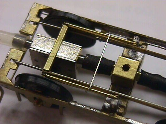
Torque reaction control in the Pendlenton bogieWith the transmission and bogie rotation axes necessarily on the longitudinal centreline of the bogie, there was no convenient additional room for a single torque reaction control bar in the same area, so Ted's torque reaction control bars are on both sides of the bogie.There are 2 sets of bars (or 'radius arms'):
For bogies with only one driven axle, see the postscript for a simpler torque reaction control system.
|
|
|
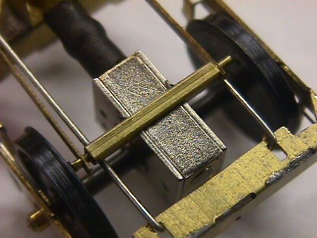
Torque reaction control piecesA gearbox crossbar of 1/16" x 1/16" hollow brass was lowmelt tack-soldered onto the sides of the top of each gearbox – this crossbar has a filed slot, which allows the top lid of the gearbox to be slid out for gearbox oiling and maintenance purposes. The gearbox lid is retained in service by a blob or silicone sealant.Two pillars (also of 1/16" x 1/16" hollow brass section) were attached to the central bolster of the bogie. The torque reaction control rods (radius bars) are simple pieces of brass strip, and locate over 0.8mm pins in the gearbox crossbars and the central bogie bolster pillars. A normal fit of the control rods over the pins allows the gearboxes to articulate with respect to each other. |
Other frame constructional aspectsTransmission clearance A strong U-piece was added to the middle portion of one end of the Pendlenton frame and then the existing frame was cut away, to allow free space for the components of the transmission axis. The clearance dimensions Ted used are given, but these will depend on the dimensions of the actual transmission components used. |
|
|
Brake shoes The brakes as supplied, being designed for coach wheels, fold up with more than 1mm clearance from DMU wheeltreads.
Method of bogie pivot attachment As supplied, the Pendlenton method of bogie attachment can make the threads of the attachment bolt catch on the bogie; Ted now settles on M2 screws, passing through a collar of 2mm bore x 2.5 mm outside diameter tube, fixing into a 2mm nut in a carriage transverse body bolster of 5mm square section plastic tube. Once tightened, the nut becomes 'captive'; in this way, the bogie can rotate and move up and down smoothly on the collar, and the fixing screw is always done up tight, rather than being the pre-load adjuster, and all bogies are quickly interchangeable. The height of the collar sets both the pre-load adjustment of the secondary springs (reducing the height of the collar increases the roll stiffness of the vehicle) and also affects the ride height of the vehicle, and so some adjustment may be needed with packing washers to achieve the best combination. With the components Ted used, a collar height of 1.5mm was found to be suitable. Modifications to side frames The Pendlenton bogie was designed for 3'7" coach wheels. For the 3' wheel DMU application, Ted removed approx 1.2mm from the bottoms of the hornguides. |
Transmission componentsDMUs are powered by a centrally mounted Mashima 1224, a comparatively low-revving motor for its size, with a 13mm x 6mm flywheel on both ends. |
|
 Ted's approach to transmission pieces is to try to use cheap and readily available items that don't require complex machining.
These flexible joints are 'constant velocity' joints – shafts on either side rotate at the same angular speed. After some initial experiments with neoprene electrical insulation sleeves, silicone rubber tube (which has been found to be more flexible than the neoprene sleeving) is now used for the flexing part of the shafts between the gearboxes, and between the bogies and the motor. For it to bend freely however, it is necessary to distort the tubing with a ball bearing of a diameter greater than that of the shaft. These circular creases allow the tubing to deform without resistance, and the driven angle to change without longitudinal friction between the shafts and the sleeve (as would be the case if the tube remained parallel). 1.5 mm bore silicone fuel pipe is a good fit over the 3/32" Exactoscale gearbox shafts, and 1/8" or 3 mm ball bearings are used. Unlike conventional 'spigot and slot' UJs, the silicone tube joints do not provide axial float, and therefore telescopic intermediate shafts are required between the flexible joints. These intermediate shafts are two sizes of square section brass tube: 1/16" and 3/32", the larger being the same tight fit in the silicone tubing as the 3/32" round gearbox shaft. A subsequent development has used 1/16" square plastic section sliding in the 3/32" brass sections, which reduces the mass of the cardan shafts between the bogies and the motor. (The 1/16" square plastic has sharp corners, so it needs pushing in and out of the 3/32" brass tube section a few times to get a sliding fit. The plastic section weighs approximately 30% of the equivalent brass section.) In practice, Ted found that the telescopic pieces are not really necessary between the gearboxes within a bogie, because of the negligible change of distance between them; the slight amount of gearbox shaft end float in the gearboxes themselves and the flexibility of the silicone rubber tubing enable the gearboxes to move sufficiently with respect to each other. 
Owing to the resilience of the silicone rubber tubing, there is a slight centring effect on the bogies. In practice, this has a negligible effect on the riding of vehicles, but Ted is investigating the use of smaller diameter (1mm bore) silicone tubing in conjunction with 1.5mm shafts and 2mm diameter ball bearings. These smaller components will further reduce the cardan masses, which will further reduce any tendency to vibrate the shafts when running at speed. Sources of supply for transmission components Square section brass tube is stocked by K&S metalcentres, and Eileen's Emporium. Ball bearings can be obtained from bicycle shops or engineering suppliers. The silicone rubber tubing can be obtained from model shops specialising in aeromodelling. Pendlenton bogies can be obtained from Dave Bradwell. Electrical pickupTed and I don't agree about some things, and drive bogie pickup systems is one example. Ted likes the American system of pickup, where the wheels on one side of one bogie are shorted to the axle (Ted used Bill Bedford shorting wires), thereby making the bogie frame live. The other bogie is treated similarly, but picking up on the other side. The bolster plate on the underside of the floor is metal, and makes contact with the metal bolster plate of the bogies, and therefore there are no wires to release when removing the bogies. |
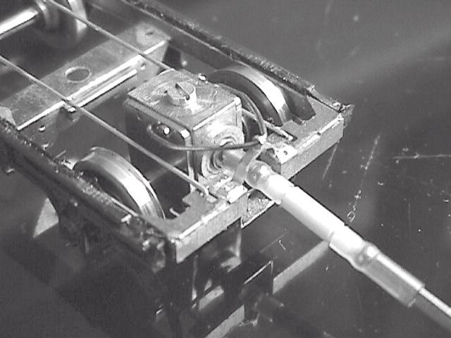
PicsHere are a couple of pictures with the Pendlenton bogies fitted with Exactoscale 18:1 gearboxes. |
|
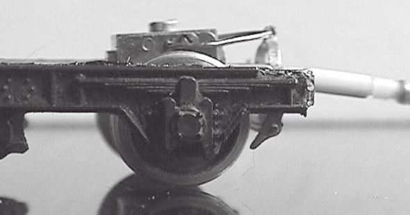
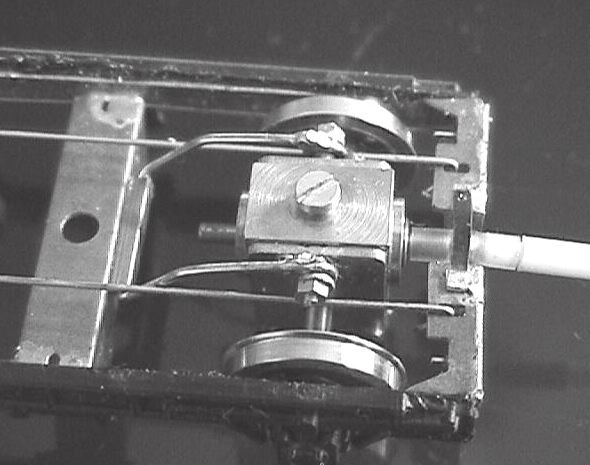
PostscriptSubsequent to the Exactoscale-fitted bogies described above, Ted fitted some prototype Ultrascale 15:1 gearboxes to Pendlenton bogies. These bogies were driven on one axle only, and this enabled a simpler torque reaction to be used. In these cases, the torque reaction rod is a loop of bent wire, holding the gearbox to either the end of the bogie frame or to the bogie central bolster. In the latter case, the torque reaction loop has been inserted into a small hollow bar conveniently sited on the bogie central bolster: the torque reaction is not entirely horizontal as can be seen, but is adequately so.postscript pics courtesy Ted Scannell
|
|
© Russ Elliott
first published April 2001
postscript added April 2003
editorial deletion of expired link March 2004
links updated September 2005
Note on new Exactoscale gearboxes added December 2005
Non-availability of Exactoscale gearboxes noted October 2013
| Return to top of page | Safety, privacy and cookies |