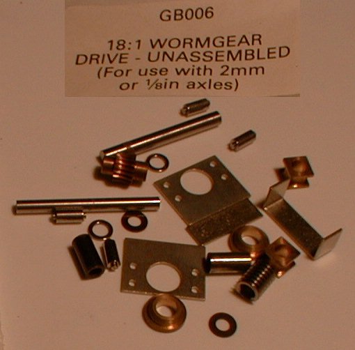
The unassembled bits
Exactoscale gearbox assembly
by Ted Scannell
Please note this page applies only to old-style (pre-2005) Exactoscale gearboxes, and not the newer ones.
This page first appeared on the Scalefour website c 2004, but disappeared in the cull of June 2010. It is resurrected here in the hope that those with unassembled items might find the information useful.
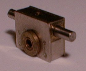
An assembled 18:1 gearbox
| In response to a query on E4um from Pete Runnacles on how to get old-style Exactoscale boxes to work, Ted Scannell describes his method of assembling them: |
|
| 1 | Bin the instructions. Hide the superglue. Expect trouble – prepare to be patient – feel lucky. Don't rush it. Take two evenings minimum. You could batch build several in the same time. |
| 2 | Degrease the worm and input shaft, and the gear and axle. Mount the shaft/axle in a chuck of some sort (a little lathe is easiest, but any type will do) so that the worm or gear is in the correct place when pushed fully on, not forgetting to allow for the thrust washers either side of the worm. |
| 3 | Add a dob of Loctite 222 screwlock and slide the worm or gear home while rotating it gently. Leave for a minute for the locking adhesive to go off, then remove from the chuck, cleaning the excess off both that and the job. Try to keep the glue out of the worm. Set aside for at least an hour, preferably overnight.
(Under no circumstances would I attempt to 'disrupt' the surface of any shaft. I have tried it before, and though it looked okay, it was no longer straight, but this discovery was not made until it was assembled and running – rough.) |
| 4 | There is a 'sharp' and a 'round' side to each of the sideplates. I ignore the instructions and fit the bearings one to a sharp side and one to a round one. This keeps each sideplate in the same orientation as its twin, so that any asymmetry about the vertical centreline due to manufacturing tolerances is minimised. This is better engineering than that suggested in the instructions.
Press the gear bearings into the sideplates with great care. It is very easy to bend the plate during this process. They should be a tight interference fit, so I fight the temptation to open out the holes, though a little chamfer with an oversize drill bit is in order, both here (on both sides) and in the cross pin holes. |
| 5 | I press each bearing in on a piece of plate glass until it is flush with the outside face, then fit two of the cross pins diagonally to each plate. At this point the two plates should look the same, but one should have sharper edges.
I fit the pins into a pin chuck and press them into their holes while rotating them slowly, but not all the way home, just enough to stop them falling out while handling. Then with a piece of 3mm rod in the drill press, and a support plate for the side plates with a hole in it to clear the bearing, the bearing can be pushed all the way home – for now. |
| 6 | After placing the gear and axle assembly into one plate, I place the other and wiggle it to ensure that the pins have all started in their holes, then apply finger pressure in the (usually vain) hope that they'll stick. Then it's into the vice jaws for a series of gentle squeezes, rotating 180 deg., 90 deg., 180, 90, etc., checking the freedom of the gear continuously, until the pins have all bottomed. |
| 7 | I now fit the wrapper, after drilling an oil filler hole and/or filing the edges if required, and seam solder the whole lot round with 70 deg. lowmelt – just in case...
About half the dozen boxes I've put together recently have had excessive end float in the axle shaft assembly. It is crucial in the design that the gear has very little – towards imperceptable – side to side movement in the box relative to the longitudinal axis of the worm shaft. It doesn't matter why, to do with tolerances I suspect, but this is the reason the bearings in the sideplates are pressed, and not glued or soldered. A proper engineer will probably tell you to dismantle the box after measuring the float, measure the bits to check, then fit the appropriate shims to the gearwheel. Reassemble saying small prayers that this will be the last time. A technician would suggest make a press tool. First, an anvil. Any piece of hard enough metal, steel at least if it's to do more than a couple, with a hole in it 10mm deep and 4mm bore at one end. I found a 6 x 4 x 14mm steel spacer tube in the toolbox, which is ideal. This slips over the bearing on one side of the box to give a firm seating. Using one of the 1/8" to 2mm sleeves provided with the box loose on the axle as a guide, I found that a piece of 1/8" or 3mm bore tube can be used to press the bearing toward the centre using the vice, a little at a time, turning the box round each time, until the gear is central and sometimes jammed! No panic, change the press tube and guide for a piece of 2mm bore tube, and a gentle push will ease the far bearing out a little via the gear. You can play around, pushing them back and forth, for hours... |
| 8 | The worm shaft and bearing assembly should be a close fit between the side tops, and the lid should clip in tight, and then, if you're reeeely, reeeeely lucky, the box will rotate down freely when the input shaft is held horizontally. |
| 9 | Where the lid is held down mechanically, as on my drive bogies, silicon sealant is strong enough to keep it on, and can be cleaned off with the fingernails for oiling purposes. If the box is to be run normal then a spot of solder each side will do, after drilling an oiling hole. If it is to be 'underhung' then I seam solder the lid with lowmelt. The oil will still come out like a Bullied chain drive, though, so packing with grease, a sump, or a drip tray where it's parked should be considered! These gearboxes are smooth in both directions from the start once assembled right, and some of them fall together directly, but others have tested my patience for no reason that I can identify. Chaos? |
| There were some followup exchanges: |
|
| Roger Howell asked: | Re use of Lowmelt – what flux do you use and how do you clean up afterwards? Red label which is normal for LM solder is midly corrosive so what's the answer? |
| Russ Elliott chipped in: | On my Exacto 2:1 RGD, I soldered each pillar in on one side of the gearbox plate, using the other plate as a jig to ensure each pillar was in the right place. I used normal electrical solder (as I did when seaming up the wrapper later on like Ted), and fluxed with my normal Eames 40, which is very mild. A quickie water washout at the end of construction got rid of any residual flux – but having water hanging around is probably worse, so the best thing is to get the box and its shafts oiled up as soon as possible. |
| Ken Walker replied: | Hi Roger, While I can't claim Ted's high level of care, I have assembled quite a few Exactoscale gearboxes (and Studiolith before them). I use regular solder for the gearbox wrappers. I generally tin before hand, then clean off flux; when the time comes to install the wrapper, I can then solder using resin or even nothing, without trouble. |
| and Ted himself replied: | I'm not entirely sure... I was given a bottle of all-purpose flux about 15 years ago by Dave Riddles, an industrial chemist, and member of the Andy Scales group at Romford at the time. I remember him saying that it was a simple dilute mixture of acid (phosphoric, 8%, I would guess, now), water, and a few drips of washing-up liquid.
It's not always possible, but in this case I use a very small amount of flux, and leave the iron on the job until well after the fizzing stops to be sure that all the flux has evaporated. The only parts that are in danger of rapid corrosion are the steel shafts, and they don't get any on them, but rinsing in warm water, again with just a few drips of Fairy suffices since they are going to be full of lube shortly. For complex fine brass work I have a piece of 1mm bore tube fitted to a bush which goes onto my air supply at 30psi for blowing water out of crevices. Great fun, too, but eye protection is essential. |
June 2010
| Return to top of page | Safety, privacy and cookies |