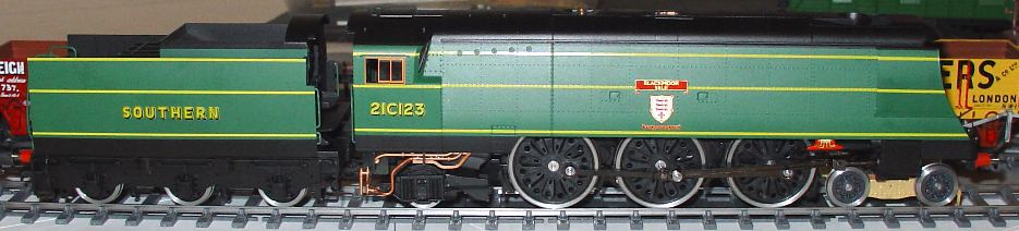
pictured by Ashley Pollard
Notes on converting the Hornby West Country to P4, using an Alan Gibson wheelset conversion pack
by Ted Scannell
These notes assume you are happy with the dismantling of the Hornby model to start with, and that you have access to a reasonable modeller's toolkit. You will need some experience of cutting small tubes squarely and accurately. A 'tube cutter' will not do...
The main difficulties are in the bearing and spacing of the loco wheels, as well as getting the crankpins true in the wheels. In the Alan Gibson crankpin pack are some long bushes for the centre crank. Place the driving wheels face down, and hold a long bush down over the hole, by the flange, with a pair of tweezers. This will keep the crankpin square while you screw it in to form the thread. Then you have to take it out again, but it is much more likely to go back in square if you've formed the thread in this way first.
Some people like to drill the crankpin hole through with a 1mm drill first, so that the thread isn't formed at all, but then it's more tricky to get the nuts on later unless you've glued them in, which then makes it difficult to service after. I wouldn't recommend that approach, personally.
It is very important to countersink the back of the hole by more than the diameter of the crankpin head, so that the crankpin sits square. More lousy runners are caused by not doing this carefully enough than by any other single thing.
Push the axles into the wheels very carefully the first time. I use a watchmaker's lathe with a tailstock chuck, with the wheel in front of the main chuck. After the axles have been through, and you can see that they are square, they can be taken out again and they'll go back true unless you're really brutal. With the lathe I can fit the crankpins first, but if you don't have access to one, it'll probably be easier to fit and then remove the axles, then fit the crankpins, then refit the axles.
You'll need some 2mm bore brass tube, o.d. not important but 3mm is very handy, and also some 3mm or 1/8" bore brass tube. The 1/8" stuff is a bit sloppy, and will be tight in the plastic frame either side of the rear, sprung driving axle. A careful wipe of both sides of both guides is required here if that axle is not to move unrealistically fore-and-aft when the wheels are spinning. It's better to find some that fits here, though I didn't. Eileen's Emporium stocks these metric tubes, as do more hobby shops now that there is a K&S metric centre.
Also – and this is a top tip for this model, a pack of 1.5mm small brass frame bearings (Alan Gibson) are very useful. These take up the difference between the Gibson crankpin bushes and the 3/32" holes in the Hornby rods. Looking at the pictures of the real thing, they are pretty close. Not needed if you are going to change the rods at the same time, of course.
If you want to retain the speedo drive, remembering that most were not fitted, if at all, until the beginning of the 1960s, you are on your own, but remember to not cut the left rear crankpin too short until you've decided how much of the pin you'll need.
If I remember clearly, the tender and the bogie are straightforward, spacing with pieces of 2mm bore tube to leave a little play, and that's all they need.
The pony truck is the worst. The axle is retained in the truck by a keeper plate, which is rivetted in place. I drilled out the rivets with, iirc, a 1.4mm drill, so that I could then tap the holes 10BA and hold the keeper plate in with short screws. I found that the pony wheels, back-to-backed at my standard 17.82mm, only just fitted in the space available. So I attacked the inside faces of the pony truck with a file until I'd had enough. The problem I found then was that, since the truck itself is live to the chassis and one of the running rails, with so little clearance, the wheel rim on one side sometimes shorts against the truck. My fix was to cut a piece of the 2mm bore tube very carefully, to fit on one side of the axle only, to keep the wheel on the other side from making contact with the truck inside face.
It's a bit of a game with the driving axle spacers, as they are all different. I made no special allowance for sideplay in any of them, just making sure that there was some, but not a lot. If you have some 3mm bore washers, or if you can cut very thin lengths of 3mm o.d. tube, it's an idea to cut the tube spacers deliberately short, and then pack them to fit with washers. Either way, it's worth taking the trouble to get these right, so I wouldn't do this job in a hurry or to a deadline.
There was one other thing with the Hornby model that I changed. The piston rods seemed to bottom in the cylinders at their maximum forward stroke, causing poor running and the cylinder block to bob up and down. I don't know if this is common or I had a Friday one. Don't shorten the piston rod if yours does this, it'll fall out of the cylinder on the back stroke! The cure was to put a small burr in my minidrill and cut out the backs of the cylinders where the notch is. This lets the piston rod travel all the way forward without clouting the end, and causes no other difficulty.
Okay, I think that's about it.
© Ted Scannell and Ashley Pollard
February 2005
pic of Ashley's converted model added October 2006
| Return to top of page | Safety, privacy and cookies |