Somersham
by Russ Elliott and Dave Haswell
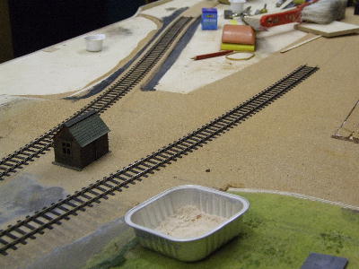
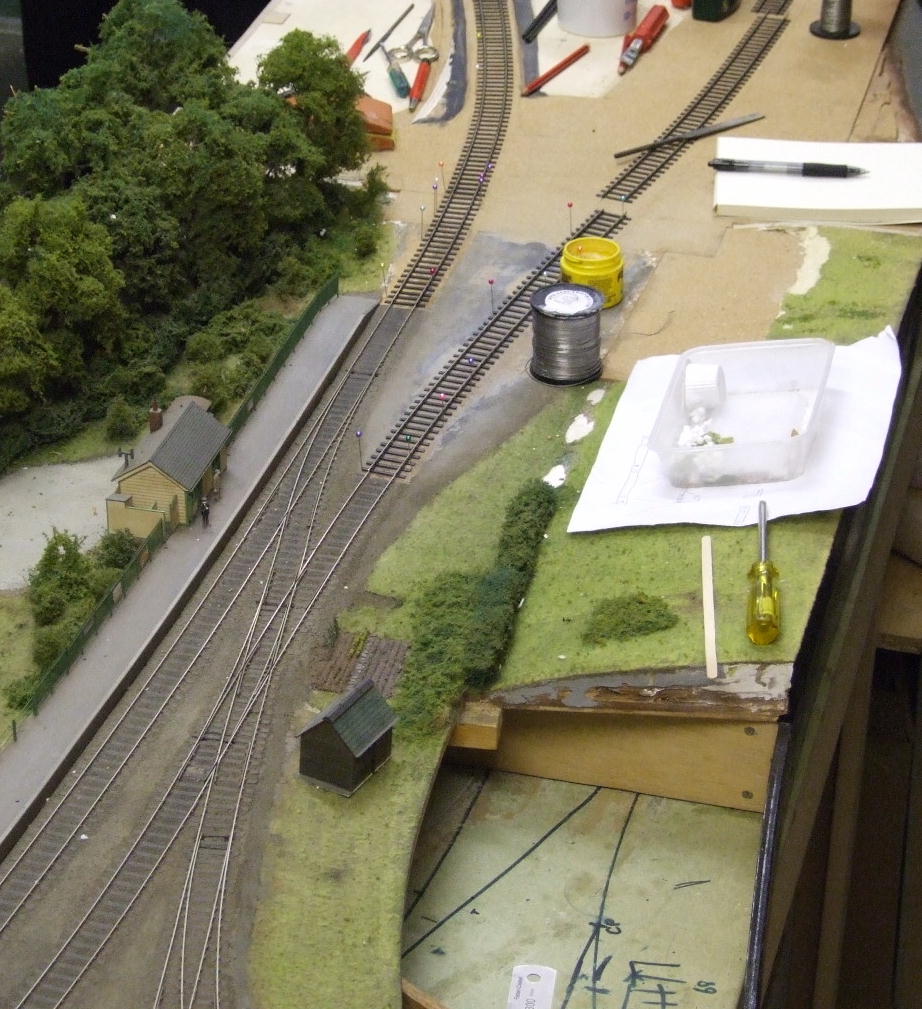
Soon to disappear under the Beeching cuts of the early 1960s, Somersham is a quiet little station on a rural byway somewhere in Suffolk. There are a few passenger trains in each direction, and the occasional goods train calls to shunt some wagons in the small goods yard. It's the kind of place where not much happens and the staff spend most of their time cultivating their vegetable patch.
The layout was built originally by Pete Runnacles as a branch terminus. Dave Haswell acquired the layout in 2005, and we converted it to a through station, which added a bit to the operating potential.
Recently, we decided to develop the through station idea by adding a new board to the layout.
|
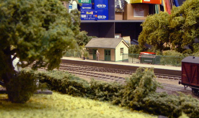
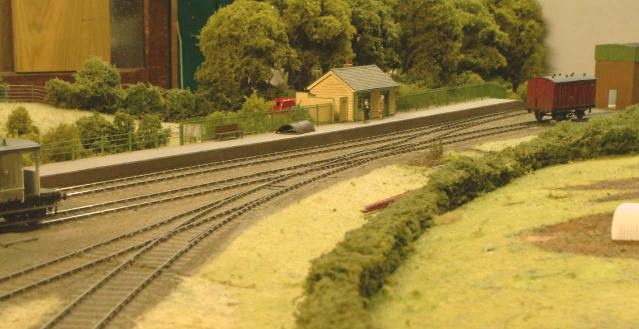
(the two pictures above are the layout in original format)
|
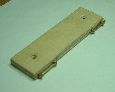
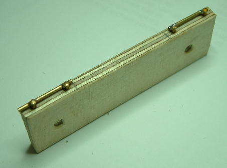
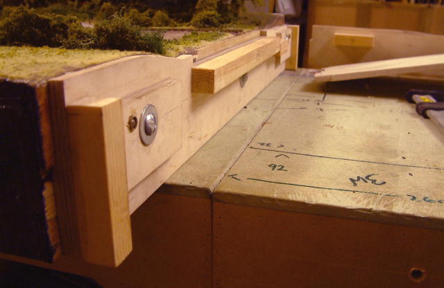
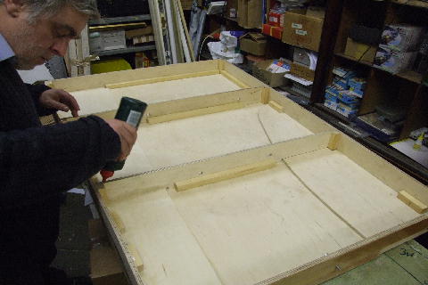
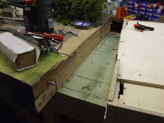
The first stage in building the new board was the new interface to the existing layout. This entailed considerable fitting, since that end of the layout had not been designed to accept an interface, and nothing was square or straight. This is the endpiece of the new board, with custom-made dowels and M6 locking bolts. The M6 washers are epoxied in place to the wood, which speeds up baseboard bolting and unbolting times.
|
|
| The rest of the new board under construction (9mm ply and 20mm batten). The top of the board isn't all at one level; there are lower layers for the ploughed field and the millpond. I remembered to put cabling holes in the board stretchers. | 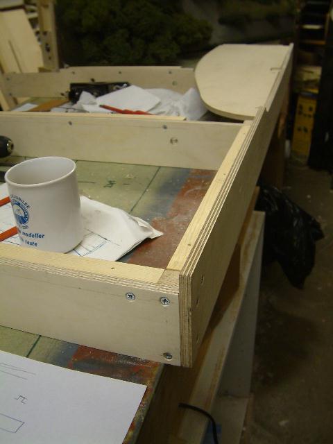 |
|
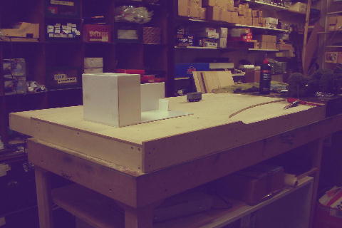
The underside of the board being completed, and the new board substantially complete (with a mockup of the proposed mill).
|
|
|
After removal of some of the old track, a new cork layer was set in on the old board.
|
|
|
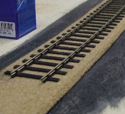
The old track area sanded smooth ready for new track panels. The bond of C&L flexi to cork is not all that strong with a thin layer of PVA, and I was a bit concerned over the vulnerability of the rails at the ends of boards, so panel pins were put in underneath the rail positions to which the rail would eventually be soldered after track laying. Holes have been drilled in the trackbed for the rail droppers.
|
|
|
|
3mm cork sheeting fixed to the new board. It sands flat easily. Some flexi track is in approximate position. The coal office building in the pictures above acts as a standin for the proposed signal box.
|
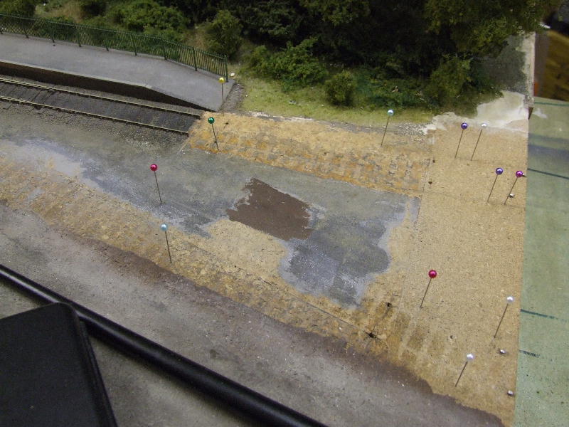
To represent the ballast shoulder on the country section, the cork sheet is cut at approximately 45º with a Stanley knife and smoothed off with a sanding block. The ash cess has been washed over with dark grey water paint.
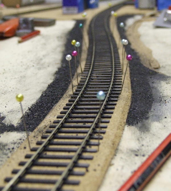
After a thin PVA layer, the ash cess has been sprinkled with crushed coal. All rail sections have been fitted with 24SWG tinned copper wire droppers (two droppers per rail length), and the track is positioned with pins to check alignments, but is not fixed yet. Rails are cut through fully (to allow expansion), with a maximum rail length of approx 500mm. Intermediate (60' lengths) cuts are made only through the top half of the rails. Cosmetic fishplates will be added later.
|
|
|
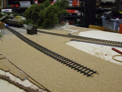
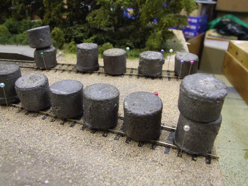
At last, some track laying. A thin layer of PVA is applied to the cork. The track sections are lowered into place, the pins retaining accurate positioning, and the droppers going through their trackbed holes. Ballast (a mix of brown, grey and buff fine-grade Woodlands Scenics) is then sprinkled on from a height of about 6" into the PVA. The thinness of the PVA layer means that only a single layer or so of the ballast will attach itself sufficiently in the PVA, but this suits the thinness of the C&L flexi base. Weights (sandcast lead using a Humbrol paint tinlet as the mould recesses) are used throughout the process to prevent any ballast from getting under the track base. When the PVA is dry, the excess ballast will be brushed off.
|
|
Somersham turnout operating units
All four of the Fulgurex point motors had originally been mounted vertically on underbaseboard transoms. Their wiring tags were close up against the underside of the baseboard, which rendered them inaccessible. The transoms had been fixed by screws from the topside of the boards, and were also inaccessible owing to track and scenic work. Following a local show, and as part of the complete rewiring of the layout, I resolved that the point motors should be repositioned and fitted with decent TOUs.
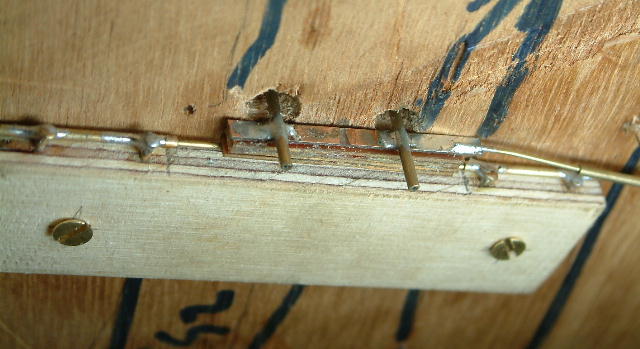
Somersham's turnouts have a 0.7mm diameter dropper wire attached to each point blade. These wires extend down through holes in the baseboard. The actuator, pictured on the right, underneath the baseboard, is a piece of gapped copperclad paxolin (sleeper strip) with two brass tubes soldered onto it. The tubes engage with the blade dropper wires.
|
|
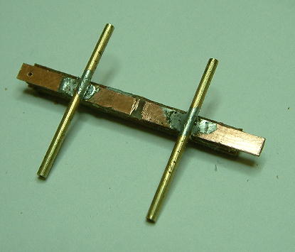
Each TOU base unit is a piece of 6mm ply with 4 brass pins inserted, onto which two pieces of brass tube are soldered. (I tried MDF first, but it split too easily when the pins were inserted.) The brass tube allows an easy sliding fit for 0.9mm diameter wire. The between-tube length of the 0.9mm wire holds the actuator reasonably in its design planes. The actuator is backed with further pieces of copperclad sleeper strip, and soldered to a piece of 0.9mm wire inserted through the tubes.
With the actuator soldered to the sliding wire in the base unit, the base unit is positioned and screwed to the underside of the board, following which the operating rod from the point motor is soldered to the actuator. The pictures show why I backed the actuator with several pieces of copperclad, to ensure clearance between the operating rod from the point motor and TOU base unit pins and tubes.
|
|
|
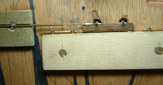
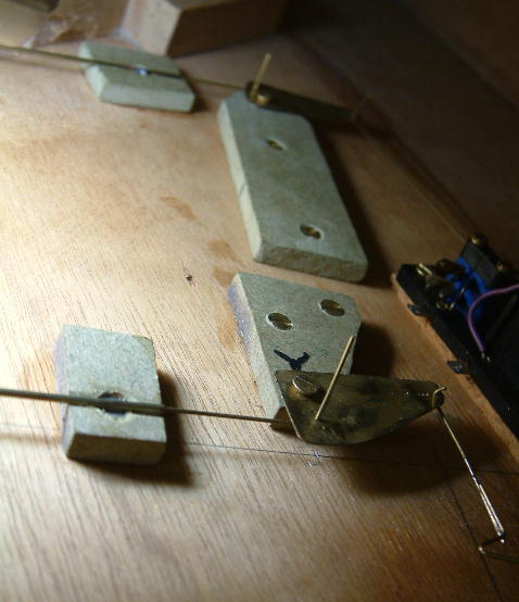
The operating wires from the point motors are 0.9mm diameter wire, constrained where necessary by running in pieces of tube. These pieces of tube are soldered to the heads of screws in MDF blocks. Homemade 4:1 ratio brass cranks transfer the movement from the Fulgurex point motors to the TOU actuators. There is approx 8.5mm movement from a Fulgurex, so the 4:1 stepdown at the crank allows approx 2mm movement at the TOU itself. Some slack is of course taken up in the fits of wires in their holes and the flex of the wire, and between the turnout blade dropper wires and their actuator tubes. A Z-loop tensioner is fitted in the point motor leg of the operating rod to ensure that the TOU actuator is gently pressured at both ends of its movement.
|
|
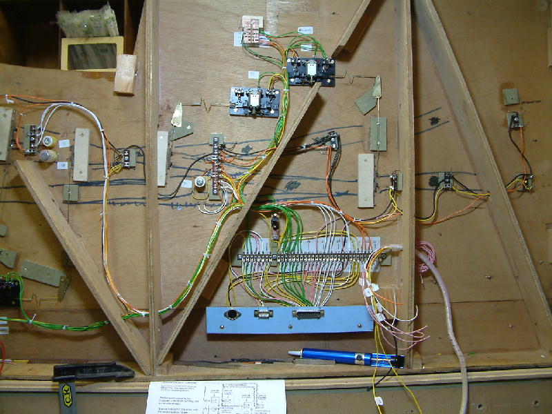
The underside of the main board, showing the new wiring nearing completion, with one of the interconnecting board leads (bound with 'Spiralwrap') awaiting connection to the main tag strip. The connectors on the blue strip at the bottom are for controller, power in, and control panel.
Although I've used a colour coding here for the wiring, I'm not convinced about the need for colour coding provided there is a decent wiring/connection diagram.
|
|
© Russ Elliott and Dave Haswell
28 March 2008
updated 13 June 2008 with TOU description
updated 5 August to show wiring progress
to be continued
|