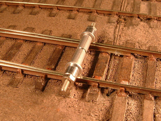
A '+0.1mm' constructional track gauge sitting on the diverging path of a turnout. The gauge is one of a set of four by Exactoscale. (Exactoscale item 4XX TG01, P4 track gauges.) photo: Ted Scannell
|
Easing the traverse through switches
by Russ Elliott
Most of this page first appeared as a letter in Scalefour News 154.
John Anderson's Voyage of Discovery article (Scalefour News 151) made a number of valuable points, and I think he's absolutely correct to draw attention to the need for adequate sideplay on any middle axle when traversing a diverging switch. The need for sideplay brings into focus our gauging practice in this area.
Constructionally, we need to ensure the planed section of the blade makes intimate contact with its stock rail over the whole length of the planing. There can't be many Scalefourers who haven't struggled with getting switchblades to fit snuggly, and any stretcher bar arrangements that create a more or less rigid box between the blades make it even harder to get the blades to fit the stock rails properly. The danger here, particularly for the diverging road setting, is a likelihood that the running rails can be under-gauge anywhere or even throughout the length of the planing.
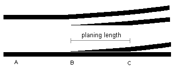
Imagine a typical 0-6-0 or 3-axle bogie traversing a diverging switch. For a straight-planed switchblade (see Martyn Wynne's 'Real track'), each axle undergoes an abrupt angular divergence as it traverses the switch blade and the stock rail. The limiting condition in respect of sideplay will normally be when the three axles straddle the switch ('ABC' in the diagram) and the middle axle is at the tip of the switchblade.
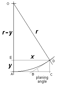
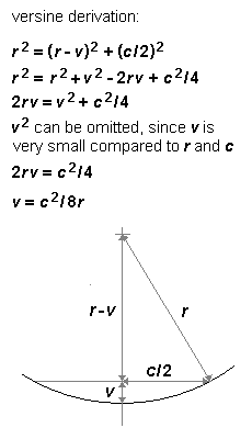
We can represent the diverging switch blade geometrically to determine the effective radius r presented by the planing angle. CD (= y) represents the width of the railhead. Applying Pythagoras:
r2 = x2 + (r – y)2
multiplying out and rearranging terms, we get:
r = (x2 + y2) ∕ 2y
Planing lengths in 4mm scale are 22mm (an angle of 1:24) for an A-switch, and 29.3mm (a 1:32 angle) for a B-switch. If we use the distance BC in the above diagram to represent the planing length, then the effective radius r presented by the planing angle is in the region of 1050mm for an A-switch and 1860mm for a B-switch. A more thorough examination of effective radius for the wheelbase as a whole is by calculating where the wheels actually are as they straddle the switch and then working back from that (by a versine calculation – see below) to the equivalent radius represented, i.e. as if it were plain track. This can be found in Martin Wynne's 'A or B switch?' page. This approach shows the wheel to chassis sideplay requirement for a typical 0-6-0 is in the region of 0.7mm for an A-switch and 0.5mm for a B-switch, and yields sharper equivalent radii, in the region of 814mm for an A-switch, and 1090mm for a B-switch. (And don't forget, sideplay requirement has to be applied on both sides of a chassis.)
However one analyses the situation, the overall messages are clear. A-switches have undesirable consequences for any 3-axle vehicle, and for both A- and B-switches, their effective radii are within the range of curvature that we would (normally) apply gauge widening to on plain track. Even with the incorporation of adequate middle axle sideplay in the chassis, any undergauge throughout a switch is asking for trouble, and a modicum of gauge widening, say 0.1mm, applied an inch or so before the blade tips and continuing throughout the length of planing, is therefore no bad thing.
|
|
© Russ Elliott
July 2009
| Return to top of page | Safety, privacy and cookies |