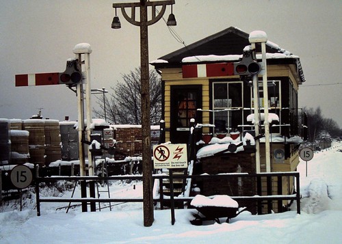
Addiscombe, Elcot Road's prototype inspiration, captured on 9 February 1991.
Image by Hectate1, via flickr.
A summer July 1993 version of this view taken by Ian Baker can be seen at the Disused Stations site.
Signalling for Elcot Road
by Mark Tatlow
This page is based, with permission, on articles first appearing in the October 2012 and November 2012 issues of Rail Express Modeller
Introduction
I must confess, I like making signals.
Partly this is because I do not think many other modellers are into them, so it is easy to be a little different, but mostly it is because they are so individualistic. Even with recent developments from Dapol, there are simply so many different variants it is impossible for an RTR manufacturer to offer more than the most basic of signals. After all, they would have to deal with brackets, dolls, calling on arms, repeaters, shunt signals, gantries, upper quadrant, lower quadrant and we have not even started on colour lights or ground signals yet! Not only are there different types of signals, there are also different styles. It is perfectly possible in many instances to determine what company signalled a station from merely the nature and layout of the signals with neither a train nor railway architecture visible.
At the time Elcot Road is set there would be relatively few unaltered pre-group signals remaining but by their nature signals can have a long life, so there will have been numerous signals either constructed in the 'big four' era even though this was 40 years previous. One of the most characteristic style of signals of the time were the rail-built signals adopted by the Southern Railway and continued by the Southern Region until quite recent times.
A whole series of types of signal were developed by the Southern to cater for most situations where a gantry was not required, but given the relative simple nature of Elcot Road's track plan, we are interested in a pair of simple post signals, one of which will have a shunt arm in addition to the main arm. This article looks at how these two signals were made and how they are made to work, including how they can be configured to bounce like the prototype when they are operated.
Making a start
Just because signals are so individualistic does not mean that they need to be a challenge to make requiring significant scratchbuilding. By their nature they were predominantly made from a combination of standard components and the kit manufacturers, notably Model Signal Engineering, have followed suit. Therefore, by combining the relevant products, it is possible to create your own kit to build your signal from. Andrew Hartshorne, the proprietor of MSE, is very helpful in selecting what components you need to build your desired signal – just take a photograph or drawing of what you are aiming for and he will assist. In the case of these kits, MSE etches S0012/01 (for the bulk of the components), S0012/02 (for the shunt arm), S0011 (for the S on the shunt arm), S009 (the ladder) and LENS (the spectacle glazing) were used.
With all the variants that are possible, identifying what is required can be daunting. I was helped that Elcot Road's inspiration, Addiscombe, has two well photographed signals. In addition, Southern signalling is well described in Prior's book A Pictorial Record of Southern Signals and there is information available from the Southern Railway e-mail Group.
The Signal Post
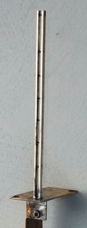
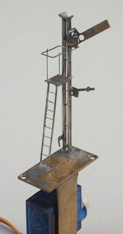
The basic post, formed from two lengths of bullhead rail, as the real things were. These are spaced apart and secured by 0.5mm wire. The dimensions for the height of the post and the distances between spacers were taken from the drawings in Prior's book.
Where the signal did not include brackets, the Southern used a pair of rail lengths to form the post and these were held apart and secured together with a series of bolts up their length. Whilst MSE offer a cast white metal post for a rail built signal that includes all of this, I elected not to use this as I was concerned that Elcot Road's signals might become damaged as the layout goes through the rigours of being taken to exhibitions. Instead, I elected to make my own posts with lengths of nickel silver rail. I soldered these together, making sure that they were properly parallel and then I sweated this onto a sheet of copperclad large enough for me to securely hold on to. Holes (0.5mm) for each of the bolts were drilled through web of the rail, utilising the drawing in Priors' book to set them out – the use of the copper clad as a carrier made this a lot easier and reduced (but not eliminated!) the number of broken drills. Separating the 'matching pair' of posts, the bolts were formed using 0.5mm wire and the two posts secured in place so that they were a scale 6" apart.
Arms and Balance Weights
|
|
Most semaphore signals were operated by simple mechanical linkage back to the signal box, so relied on the signalman to operate them. To ease the burden on the signalman's muscle power, the arm was counter-balanced by weights appearing either at the base of the signal post or, as in these signals, mid-way up. Whilst I did revert to the MSE components to make these, I found that the actual levers provided by MSE were too slender to be durable. Instead, mine were fabricated from 0.3mm brass sheet through which I had drilled 0.4mm holes for the operating wires and a 0.5mm hole for the central pivot. The MSE counterweights were then added to this and also their bracket for supporting the levers. When I soldered this in place, to prevent myself from accidentally soldering it solid, I utilised sheets of very thin paper (cigarette paper). These are slipped between components as the pivot wire is inserted and once the wire is fully in place I touch the paper with some light machine oil. After this has permeated fully across the paper it prevents solder flashing across joints and locking the moving parts together.
One of the key requirements for signals to behave realistically is for all of the pivots and rods to be snug in their bearings. It is therefore essential to ensure that the holes are sized to be just right for the wire that you use within them. If they are not, then there will be too much slack in the operation resulting in an unrealistic jerky movement. Guitar wire is used to connect the arms and the balance levers; this is available in 0.03mm increments, so it is very easy to select exactly the right thickness wire to suit the holes that you have drilled and it is stiff enough to push the arms where this is necessary.
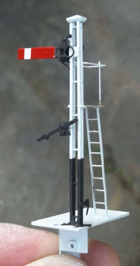
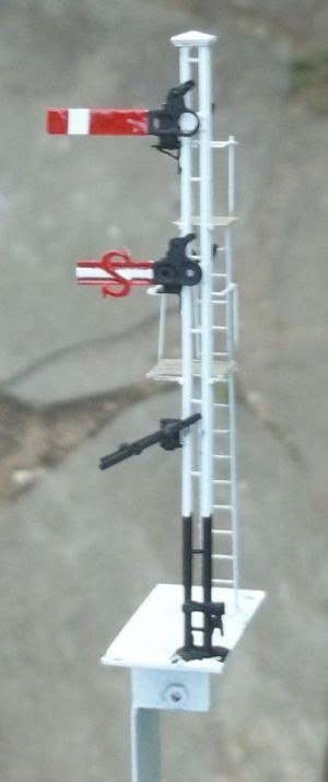
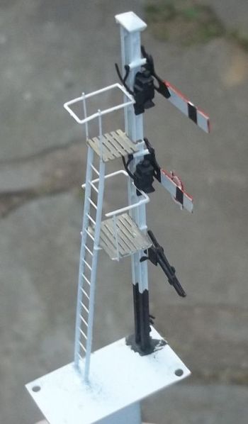
The principle arm for the starter signal comes from MSE kit and the only modification I made to it was to laminate a thin overlay to the arm where the signal operating cable affixes; I found it too delicate otherwise. The Southern utilised shunt and calling on arms rather more than any of the other railway companies and also modified these by reducing the aperture of the spectacle plate to merely a small dot. I presume that this was to make it clear at night that this arm was subsidiary to the main arm that would be directly above it. As I wished to use a corrugated arm for this, I selected one for MSE etch S0012/02 and trimmed it shorter to the dimension noted in Prior's book. To this I sweated a sheet of 5 thou brass sheet onto the rear of the arm and then 0.8mm holes were drilled in the centre of the spectacle positions to represent the reduced size openings.
Bearings for the arms were formed of micro bore brass tubing, taking care to get one to the right size to snugly accept the wire spindle that had been soldered to the rear of the arm. The spindle was first soldered with a high melt solder to the signal post, so that it was less affected by later soldering exercises. The bracket for the lamp was also soldered to the post, and the lamp secured to it with low melt solder. The arms were then assembled onto the bearing and the blanking plate to the rear offered up, having first utilised the cigarette paper and oil to separate the components.
Ladders and Gantries
All signals need to be maintained and until the advent of widespread electric light, lamps needed to be lit at dusk and extinguished in the morning. Climbing up the signal was therefore a daily occurence for the signalman and access had to be provided for them. A simple ladder is not sufficent to work from except for the simpliest of signals, so landings were introduced to reach each arm – the lower landing is wider to allow the signalman to gain access from and to the ladder.
The ladder was assembled from the etched stringers that incorporate holes for each of the rung positions. The rungs were 0.4mm wire, and I think this looks much better than a flat etched ladder.
The landing for the single arm signal and the upper landing for the double arm signal were formed from those provided in the MSE etch, with one batten removed to set it to the right dimension. It was necessary however to reinforce the angles supporting the timber battens with a rod of brass, as otherwise it is too flimsy. A wider version was used for the final landing, to give the signalman sufficient room to step off and around the ladder carrying on further up. This was made from 0.7mm strip from Eileen's Emporium, supported on brass rod. A photograph of a comparable landing was used to judge the appropriate size and shape of the landing.
The MSE etch also provided the handrails to the upper landings, with more brass wire used to form the banisters. The handrail to the lower banister was formed from offcuts from the etch, sized and shaped to match the photographs. All of the handrails were formed at the end of the build, as they are delicate and prone to damage.
The Signal mount
|
|
These signals are operated by way of miniature servos of the type that our aero-modelling cousins have been using for some time. Over the last few years, much improved means of controlling servos have become available and once they have been mastered, these offer small, cheap and controllable solutions to the operation of the semaphore arms. In addition, the electronics can now offer the possibility of introducing a slight bounce as the signal arm is returned to rest, mimicking the arm hitting and bouncing back from its stop as the prototype does.
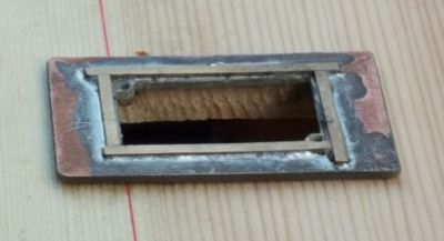
Before the operation of the signal can be considered, it is necessary to form a mount for the signal. This has been designed to allow the signal to be semi-permanently affixed to the layout as I have found that less damage occurs to signals if they do not need to be handled as they are fitted and taken away at the each end of a show. However, the signal does need to be capable of being taken off the board for maintenance and adjustment. Thus, the mount for the signal has been conceived to be just a little bit bigger than the hole that is required in the board to allow the servo to slip through it. In this case readily available "Tower Pro SG90" servos have been used and a hole of 16.5 x 32.5 mm was found to be sufficient to allow this, including a cut back servo operating arm to pass through the board. This allowed the baseplate for the signal to be 1mm wider in both axis (so 17.5 x 33.5mm) and still leave sufficient room in opposing corners of the baseplate for a 10BA countersunk screw to be located.
The baseplate was formed from a thick (0.7mm) sheet of brass – liberated from a brass push plate from a domestic door! A mount for this to sit on was then made from a piece of paxolin to a size in excess of that of the baseplate. This mount is fitted permanently to the baseboard allowing the baseplate, including the signal and operating servo, to be secured to it with the 10BA screws. It is a matter of simply releasing the screws to allow the whole thing to be withdrawn for maintenance or repairs. A socket is formed on the top of the mount to receive the baseplate by forming a bund around the baseplate with scraps of 0.7mm brass – this allows the scenery to be finished tight to the baseplate and the joint becomes almost invisible.
To the underside of the baseplate a support for the servos is formed from a plate of the brass folded into an L angle and a cut out made to one face of this to accept the servo. This cut out was sized 23mm to allow the servo to be mounted on its end, presenting the smallest face to define the minimum opening in the baseboard. Where multiple arms need to be operated from the same post the servo support can be extended to allow further servos can be mounted below, although baseboards will need to be sufficiently deep to accommodate multiple servos.
Operating the Signals
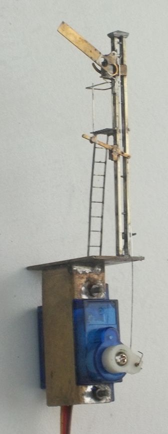
The mount for the signal comprises of a piece of brass rebated to accept the servo mounted vertically.
Servos have only recently been used by railway modellers but provide a number of possible uses to us. They utilise a small motor geared to twist the operating arm through approximately 180° and only a small amount of this rotation is necessary to operate a semaphore signal. To be able to utilise servos in our applications, a means of determining what degree of the arm throw is required in the rest and active states, corresponding with the signal arm being on or off. The servos on Elcot Road's signals are now operated by servo controllers produced by MSE but they have also been operated by a similar controller available in a kit form to members of MERG, and there are alternative controllers offered by Full Stop Signals. Each of these offers different characteristics and the MSE one was chosen, despite being the most expensive, because it allowed local control without the need for a separate device to adjust the throw and characteristics of the servo operation.
The MSE servo controller comes preassembled and the first task is to connect the servos to it. The servos that were used, like most servos, come with a female cable socket hard wired in place which is connected onto the corresponding male connection on the controller. The operator commands the servo controller by a simple switch which makes or breaks a wire loop that comes out of the controller. The final task is to power up the controller, in the case of the MSE version with a 12V DC supply.
Prior to connecting the signal to the servo, it is necessary to first power up the controller so that it can be set at its mid throw. This is necessary to ensure that the signal can be set up properly and control the signal. A link to the balance lever is formed in the same manner as the signal operating wire, with guitar wire passing through a hole in the signal base. The hole in the servo operating arm is much larger than the wire and thus it is necessary to sleeve this to ensure there is no slack, as this would translate into an unrealistic operation. Once it has been determined, by twisting the arm of the servo, that the throw of the servo arm will operate the signal arm from on to off, it is possible to set the servo controller. The controller has a series of potentiometers that can be operated with a screwdriver to set the upper and lower limit of the throw of the servo – this is very sensitive and it is possible to adjust the angle of the signal arm down to a few degrees. The danger position of a prototype signal is achieved by the arm coming to a rest on a physical stop, so it tends to be at or close to horizontal. Whilst the off position is intended to be at 45°, this was defined by the operation of the signal and thus depends on how well the signal was adjusted so was much less consistent (despite what the rule book said!).
As semaphore signals move to the on and off positions they bounce where they reach the limits of their travel and the physical stops. Upper quadrant signals such as these bounce most noticeably when they return to danger, but they do also bounce when they are pulled off. The MSE servo controller includes a further pair of potentiometers that can be used to allow the arm to bounce; one each for the bounce at each end of the travel of the arm. The potentiometers allow this to be set from a minimal amount to quite a substantial bounce, and it pays to review film clips of signals in action, or watch one yourself, to assess how much they bounce.
A servo control board produced by MERG for its members allows for up to four servos to be controlled, with their upper and lower travels and speed all capable of control. With some reprogramming of the chip, it is also capable of making the arm bounce at the end of its travel.
Painting
Once the signals have been finished, and prior to any painting, the signals were properly cleaned and prepared. The first stage is to soak them in hot water and lightly scrub them with an old toothbrush. Do not use washing up liquid for this as this has lanolin as an additive that remains after it is rinsed, affecting the bond of the paint. Instead, use Shiny Sinks or a cream kitchen cleaner. To remove fine muck (especially those horrible bits left by a glass fibre pencil) I also repeat the clean in an ultrasonic bath. It never ceases to amaze me how debris is released by this, even after I think I have cleaned the object well before using it!
With any metal to be painted I now always grit blast them using a Humbrol grit gun and aluminium oxide grit. I find that this provides a much better key for the paint, even with a strong primer. Even so, it is still appropriate to use an etch primer (in this case the two part version from Precision Paints); it adheres much better than the car aerosols. However, car aerosols do provide the most convenient way of painting the base colour of white and being cellulose paint dries very hard and quickly.
As there are a number of boundaries between paint colours that need to be crisp and straight, it is best to mask these. It is best not to use DIY type masking tape, instead I use Tamiya Model masking tape that gives a much crisper edge, is low tack but does not allow paint to creep below it. I utilised this to mask the top of the base and, particularly, the colour boundaries on the arm – this makes getting a good finish relatively simple. However, having used cellulose for the base paint, a trick is to use enamels for the following work as if a mistake is made then it can be removed with enamel thinners as they do not affect cellulose paint. Signals generally, but especially on a secondary line such as that which Elcot Road is seeking to represent tended to be rather uncared for, so a good dose of weathering is required. The final stage is to glaze the spectacle plates. MSE provide coloured sheet of the appropriate colours, which I secured utilising matt varnish as to use glue runs the risk of 'whitening' the sheet plastic due to the affects of solvent.
© Mark Tatlow
February 2013
| Return to top of page | Safety, privacy and cookies |