Bearing and axle interfaces
for coaches and wagons
|
by Russ Elliott
Drawings are not quite to scale, and dimensions are in millimetres.
|
26mm pinpoint axle and bearing interface
The traditional 'standard' for the 26mm pinpoint axle interface is where the point of the axle and bearing is located 1mm from the rear face of the flange of the bearing. This setting provides for a 24mm dimension between the inside faces of W-irons or bearing carriers. An earlier standard for the interface was the Model Railway Study Group (MRSG) design, where the point of the axle was located 1.25mm from the rear face of the bearing flange.
|
|
The body of the standard pinpoint bearing can be either of the 'parallel body' or 'waisted' form, the latter form needing less clearance in the recess of an axlebox casting or moulding fitted to the outside of the W-iron or bogie frame. Both share the same 2mm diameter body to fit into a standard hole in a W-iron, bearing carrier or bogie frame.
On the right is the manufacturing drawing of the standard pinpoint bearing, adapted from the original Mike Trice drawing of 1982, showing the interface with the 2mm diameter pinpoint axle.
|
The pinpoint axle principle The pinpoint principle is derived from watch and clockmakers' practice, where both shaft and bearing are radiussed. In these environments, shafts are not subject to significant side forces, and bearings are held rigidly in position in the framing of the clock or watch. In our model coach and wagon environments, bearings cannot be held so rigidly in relation to each other, and the bearing and axle are subject to significant vertical force (from the mass of the vehicle), and thus the axle end is likely not to be running in its idealised position.
More information on jewel bearings can be found here. |
|
|
| The Studiolith axle specification The Joe Brook Smith (MRSG) drawing of 18 March 1969 specified a 55° axle end, and that the axles should be 'tumbled' ("roulage to give approx 0.05 radius to tip"), which gave an effective length to the 26mm long axle of 25.9mm. It is most likely the roulaging was specified to remove turning burrs. |
 |
Manufacturing deviations In practice, the manufacture of model pinpoint axles and bearings is subject to defects:
- axles can sometimes be fractionally underlength;
- the drills used for forming the bearing point become blunt quite quickly, resulting in a 'flat' at the end rather than a true point;
- the depth of the bearing point in relation to the body of the bearing can vary throughout the production of a batch of bearings.
Design variants Manufacturers of W-irons adopt different 'between bearing face' dimensions, for example to cater for sprung carrier systems and the need to keep W-iron widths in the solebar region to a minimum. Coach bogie widths are not usually as constrained in width as wagons.
Because of these variations, the appropriate form of bearings should be chosen to match a particular model application. Washers between the bearing and the W-iron or bearing carrier can be used to take up any dimensional leeway.
|
The Markits pinpoint bearing This pinpoint bearing form is different from the standard in that it has a slightly longer body length, a slightly different bearing angle, and, most important of all, has a significantly different depth of bearing point in relation to the rear of the bearing flange. This depth is 0.375mm more than that of the standard bearing above, i.e. 0.75mm length difference per pair of bearings in relation to the axle length.
If used with 26mm length axles without packing washers between bearing and the W-iron or bearing carriers, the Markits bearings enable a nominal 23.25mm between W-iron or bearing carrier faces.
|
|
The Exactoscale pinpoint bearing This 60° pinpoint bearing form is identical to the standard except that its point is 1.2mm behind the rear of the bearing flange. This is the design drawing of the Exactoscale parallel-body pinpoint bearing, but please note the drawing reflects the actual dimensions achieved in production.
Without packing washers between the bearing and the W-iron or bearing carriers, the Exactoscale bearings enable a nominal 23.6mm between W-iron or bearing carrier faces when used with 26mm long axles.
|
|
25mm parallel axle and bearing interface
This axle is 1mm diameter and 25mm long, and is designed to run in parallel bearings of either 2mm diameter body or 1.5mm diameter body.
|
|
|
Fitting axles in pinpoint bearing vehicles
Getting axles in and out of pinpoint bearings is easier if the bearings have a groove in the face of the flange. With the pinpoint bearing fixed in the bearing carrier or the W-iron before it is bent up to shape, put the end of the pinpoint bearing into a hole in a bit of wood to hold it steady, and file the dotted line with a triangular needle file.
|
|
A perspective on this page The purpose of this page is not prescriptive; it is intended to describe what is available and how manufacturing dimensions differ. True verticality of rocking W-irons is not necessary, and the legs of this type of W-iron can be bent in and out to accomodate the combination of axle and bearings. The need for close matching of axles in pinpoints has arisen only since the advent of sprung carrier systems, where verticality of carrier movement is necessary.
Will Litchfield writes: "On the subject of getting the axle length, bearing depth and distance between W-iron sorted out, one of the Masokits sprung W-iron kits comes with a depth gauge for pinpoint axles. It had never occurred to me just how variable these bearings might be, though I had noted significant variation between the fit of axle/bearing combinations between various kits and that it did seem a bit of a lottery if you could get a good fit with the W-irons truly vertical. If I thought about it at all, I just put it down to variations between kits or the way they had gone together.
Acquiring the Masokits gauge was something of a revelation and made me think on a bit. Having never thought this through from a proper engineering point of view, I had one plastic bag full of assorted bearings from various manufacturers. Given the gauge, I have gone though my stock of bearings and separated them into the four different depths the gauge allows me to differentiate. So now, when fitting wheels, I know I can set the W-irons vertical, then using my gauged bearings find a pair that give a good fit with the axle I plan to use. The fact that I've separated out the different depths isn't everything as there is also significant variation in the depth of the bearing flange that is important too. The revelation was that it was practical to go looking for a pair that matched the W-iron spacing and axle length I'd got. It's worth noting that the same Masokits kit came with shim washers for use if the available combination of axle and bearing came up too short."
|
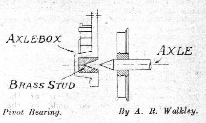
There's not much new under the finescale sun
Adjacent is a drawing by A R Walkley, a version of which first appeared in the December 1925 edition of Model Railway News in an article titled 'Reducing Rolling Friction'.
My thanks to Andrew Emmerson for supplying this historical snippet.
© Russ Elliott
First issued 2 October 2006
revised 10 October 2006 to reflect information from Exactoscale
revised 13 October 2006 to add Will Litchfield perspective
revised 3 September 2009 to add pinpoint axle angle
updated 09 December 2013 to add original NRSG bearing depth arrangement
A R Walkley drawing added 19 Febuary 2014
Studiolith axle specification added 26 October 2016
|