
Green Street turnout operating units and switchblade operation
by Russ Elliott
Our requirements for turnout switchblade operation were:
|
|
There are many ways to actuate switchblades – what follows is merely how we did it for Green Street. (A somewhat simpler variation on what is shown here can be found on the Somersham page.)
Green Street's point motors are Fulgurex. The actuators of the motors are linked to the TOUs with brass wire (in some cases via cranks, depending on the siting of the point motor under the baseboard) with omega/z-loops to take up the slack and hold the tension when operating the TOU. There is approx 8.5mm movement at the point motor actuator, and we need approximately 1.75mm at the blades themselves. Crossovers are driven by a single point motor.
Figure 1
|
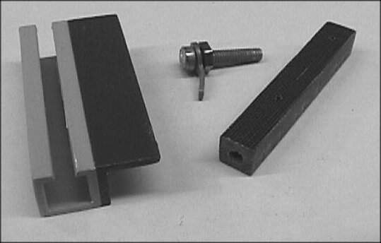
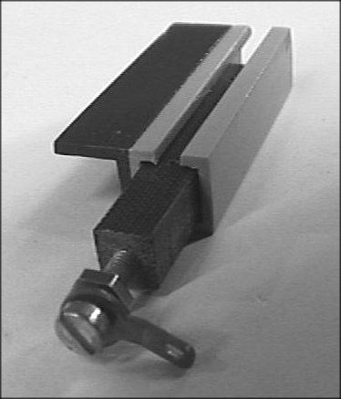
Our TOU design is a homemade version using the principles of the old but well-proven Studiolith 'curtain rail' design, with a 1/4" (nominal) square piece of paxolin moving in an ABS plastic 3/8" hollow-square section attached to an L-piece of ABS section, with an aperture cut out in the hollow-square section for the switchblade operating rods. We used paxolin as our slider material, but the only requirement is that it should be insulating, thus equivalent solid plastic section could be used. The slider is an easy fit within the hollow-square section. The TOU assembly is spaced off the underside of the baseboard by a 40 thou piece of plasticard (attached to the ABS L-section). This allows a 10 thou plasticard 'splash plate' to fit snugly over the hypodermic tubes, which prevents any loose ballast etc that falls down through the baseboard holes from getting into the TOU mechanism. The operating wire from the point motor is soldered to a tag held between nuts on a bolt in the paxolin slider. The bolt and nut(s) enable accurate adjustment of the paxolin slider, without the need to alter the lengths of the brass operating wires from the point motors, although we usually find that slight adjustment of the joint between the two parts of our blade tag assembly is the most convenient way of adjusting the degree of movement and the fit of the switchblades. Figure 1 shows 2 hypodermic tubes for a normal turnout and single slips – double slips have longer paxolin pieces with 4 hypodermic tubes. Overlapping blade set applications (e.g. in a 3-way turnout) are similar, but the 2 paxolin sliders are shaped to allow independent movement.
|
|
Figure 2
|
Figure 3
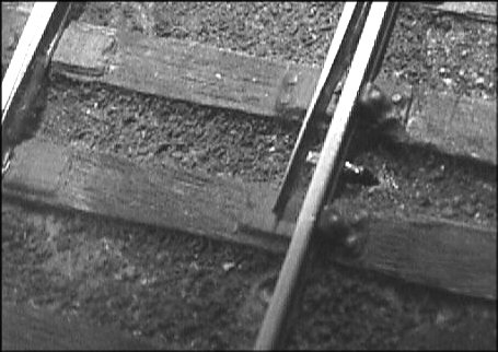
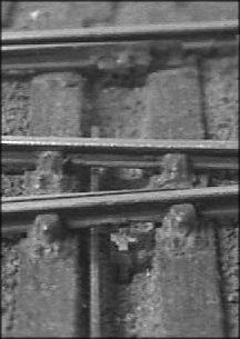
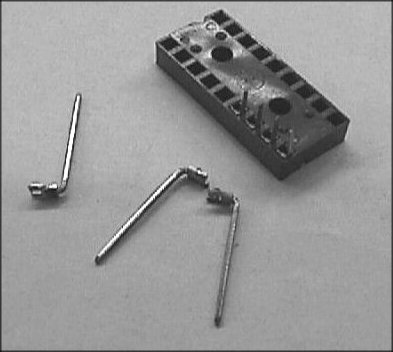
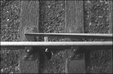
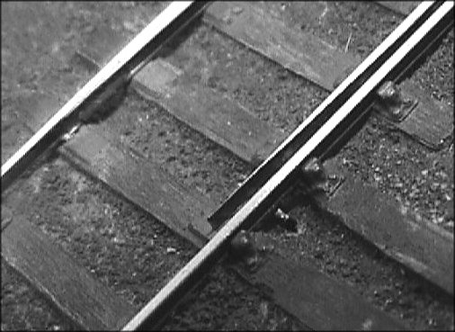
The switchblade operating rods are hypodermic tubes held (a force fit) in the paxolin, and extend up through holes in the baseboard below the ends of the switchblades. Inside the top of the hypodermics are some electrical tags from some old electronic components (dual-in-line sockets); the legs of these tags are a good fit in the hypos, but they are not secured to them, and they can thus twist very slightly (because blade movement is not parallel). The top (horizontal) part of the blade tag assembly is bent over and soldered to the blades, and lies immediately underneath the stockrail so the blades cannot lift up. The inside bore of the hypodermic needle size we used was approximately 0.5mm. As the tag assembly is not secured to the hypodermic bore, the TOU can be dropped (for servicing etc) from below the baseboard without the need for unsoldering the blade tag assembly from the switchblade itself. Small pieces of paper are glued to the top of the baseboard to give the smallest visible operating rod aperture. See figures 2 and 3.
Further attachments to the switchblades above surface level (stretcher bars etc) will be non-functional and we expect these will be in thin plastic (10 thou black) so as not to impede the separate movement of each blade (the 2 blades are not completely synchronous, owing to the flexing and takeup of the hypos).
Figure 4
The incorporation of the splash plate has prevented the major source of trouble that we ran into, namely loose ballast falling into the TOU mechanism. Even so, the 40 thou 'spacer' allows little headroom above the splash plate, and a considerable increase in this value would be preferable, as it would allow any fallen loose ballast to be blown away. A different design of TOU and operating rod, which avoids the need for splash plates, is shown in figure 4. (This variety is not incorporated on Green Street, but was adopted on a private layout of a CLAG member.)
Here's some pictures of the TOU fixings to the switchblades – stretcher bars are still to be added to these turnouts.
|
|
© Russ Elliott
March 2000
| Return to top of page | Green Street menu page | Safety, privacy and cookies |